


CHAPTER5 OPERATING
17
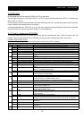
5.4 Parameter Examples
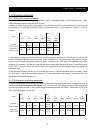
5.4.1 Writing a four byte parameter
In this first example, PPO1 is used to set parameter F002 (1
st
Acceleration time 1) to 4.00 seconds. Also, a Start
command and a frequency set-point (50%) is given.
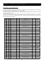
Please note: When reading/writing parameters via the Profidrive profile the cross-reference list must be used,
see chapter 5. For example, parameter F002 (1
st
Acceleration time 1) have parameter number 23 (17h) on
Profibus
.
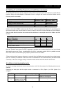
PKW PZD
Word
1
PKE
2
IND
3
PWE
4
PWE
5
STW
ZSW
6
HSW
HIW
Request:
PLC->Inverter
30 17 00 00 00 00 01 90
04 06
04 7F*
20 00
Response:
Inverter->PLC
20 17 00 00 00 00 01 90
03 31
03 37
20 00
In the request message the first two bytes are used for parameter identification. The first digit (2) denotes the
function “Change parameter value (long word)” (refer to chapter 3.2). The second digit along with the second
byte (0 and 17) indicates parameter number 23. Bytes 7 and 8 (01 90 = DEC 400) is the parameter value (400
meaning 4.00 seconds). The last four bytes are the Control Word and Frequency set-point. Control Word value
04 06 -> 04 7F* starts the motor, while 20 00 (refer to 5.3.2) signifies 50 % of the maximum frequency specified in
parameter A004.
In the response message, the first digit (2) indicates the function “Transfer parameter value (long word)”. Value
(01 90 in bytes 7 and 8) and parameter number (x0 17) are mirrored from the request. The last four bytes are
Status Word and Actual frequency (%).
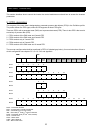
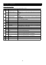
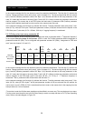
5.4.2 Writing a two byte array parameter
In this second example, we are configuring PZD3 to contain the value of parameter A038, “Jogging frequency” in
the responses from the inverter to the master (PLC). PPO2 is used. On Profibus parameter A038 corresponds
to parameter number 61 (3Dh). This is configured with parameter number 916 (394h), “Assignment of PZD read
word” (see also chapter 5.3. and 5.5).
PKW PZD
Word 1
PKE
2
IND
3
PWE
4
PWE
5
STW
ZSW
6
HSW
HIW
7
PZD3
8
PZD4
9
PZD5
10
PZD6
Request:
PLC->Inverter
73 94 01 00 00 00 00 3D
04 06
04 7F
20 00 00 00 00 00 00 00 00 00
Response:
Inverter->PLC
43 94 01 00 00 00 00 3D
03 31
03 37
20 00 01 F4 00 00 00 00 00 00