


HX200/HX200L-2000/HX300/HX300L/HX400
3-12
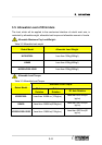
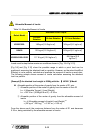
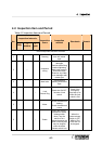
Allowable Moment of Inertia
Table 3-4 Allowable Moment of Inertia
Allowable Load Torque
Robot Model
R2 Axis
Rotation
B Axis Rotation R1 Axis Rotation
HX300/300L 150kg·m²(15.3kgf·m·s²) 30 kg·m²(3.1 kgf·m·s²)
HX400 120 kg·m²(12.2 kgf·m·s²) 50 kg·m²(5.1 kgf·m·s²)
HX200L/200L-2000
117.6 kg·m²(12.0 kgf·m·s²)
58.8 kg·m²(6.0
kgf·m·s²)
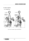
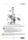
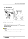
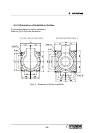
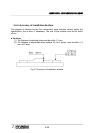
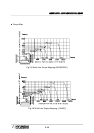
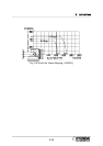
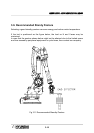
Loads must be kept below maximum conditions shown in [Fig. 3.8~Fig 3.10].
[Fig 3.8] and [Fig 3.10] show the possible range in which a point load can be
positioned, assuming the attached load is a particle. However, as the actual load(End
Effector) is not a particle, calculate and evaluate the moment of inertia on each axis.
The following exmple shows moment of inertia calculation assuming the attached
load is a particle.
[Example〕An attached load weight is 200Kg with the 【 HX300 】Model
Allowable position of the center of gravity from the center of R1 axis
① Allowable position of the center of gravity from the center of Axis R1
L
R1
≤ (Allowable Torque) / (Load Weight)
L
R1
= 687 N·m / (200Kg×9.8 m/s
2
) = 0.35 m
② Allowable position of the center of gravity from the allowable moment of
inertia
L
R1
≤ (Allowable moment of inertia/ Load Weight)
1/2
= (30 kg·m
2
/ 200 kg )
1/2
= 0.387 m( > 0.35 m)
From the above result, the maximum distance from the center of R1 axis becomes
0.35 m, being restricted by the allowable moment of inertia.