


Removal and Replacement Procedures 3-45
Rear Fan
Removal
1. Set the power switches of the attached devices to Off.
2. Set the power switch of the system unit to Off.
3. If the system unit has a rear cover, do the rear cover removal procedure on page 3-3.
4. Do the top cover removal procedure on page 3-4.
5. Remove the CPU card (see page 3-30) and the memory cards (see page 3-37).
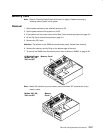
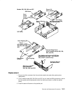
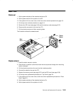
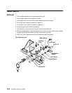
6. Disconnect the connector for the rear fan (P7).
7. Pull the shock mounts out of their mounting holes.
The illustration reflects the newest model.
Shock
Mount
Air
Flow
Rear
Fan
Replacement
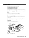
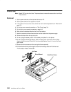
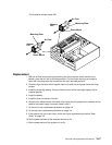
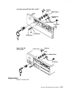
1. Install the shock mounts in the fan.
2. Place the fan in position to allow the shock mounts to protrude through their mounting
holes in the base.
3. Pull the shock mounts from the rear into their installed position.
4. Connect the cable for the rear fan (P7).
5. Replace the memory cards (see page 3-37) and the CPU card (see page 3-30).
6. Do the top cover replacement procedure on “Top Cover” page 3-4.
7. If the system unit has a rear cover, do the rear cover replacement procedure on “Rear
Cover” page 3-3.
8. Set the power switches of the attached devices to On.
9. Set the power switch of the system unit to On.