


2-1520-2
Installation and Service Guide
Step 1
Be sure that the external power cable to the system unit has continuity, is plugged into both
the system unit and the power outlet, and that the power outlet has been wired correctly
with the correct voltage
Did you find a problem?
NO Go to Step 2.
YES Correct the problem. Go to “Map 0410: Repair Checkout” in the
Diagnostic
Information For Micro Channel Bus Systems
.
Step 2
(from Step 1)
1. Set the power switch on the system unit to Off.
2. Follow the procedure in “Top Cover Removal” on page 3-4.
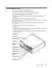
Attention: P2 and P25 must be connected and disconnected at the same time.
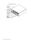
3. Disconnect the P2 and P25 power supply connectors from the system planar.
4. Disconnect the power connectors P3 and P4 from the disk drives or from the system
planar.
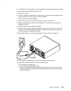
5. Connect the power cable.
6. Set the power switch on the system unit to On. Wait 10 seconds before answering the
following question.
Did the power-on light come on and stay on, and are all the fans running
continuously?
NO Go to Step 3.
YES Go to Step 5.
Step 3
(from Step 2)
Did the power-on light come on and go off?
NO Exchange the power supply. Refer to the “Power Supply” removal
procedure on page 3-16. Go to “Map 0410: Repair Checkout” in the
Diagnostic Information For Micro Channel Bus Systems
.
YES Go to Step 4.