


4-6 Installation and Service Guide
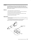
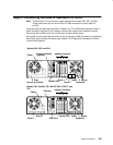
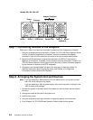
Power
Tablet
Parallel Port
Keyboard
Mouse
Ethernet
SCSI-2 PortSerial 1 Serial 2
S 1 S2
P
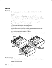
Models 380, 390, 39H, 397
Adapter Positions
1234
Step 7. Connecting Devices to the Adapters
Refer to the “About Your Machine” document to determine which adapters are installed.
1. Using the customer planning information, Chapter 3 of
7012 300 Series Operator Guide
,
or other information supplied by the customer, connect the cables to the adapter
connectors. Start at the left connector and move to the right to make cabling easier.
2. Record the SCSI addresses of the devices attached to the SCSI I/O controllers in
Appendix A of this book. If needed, use the customer planning information, Chapter 3 of
7012 300 Series Operator Guide
, Appendix A of this book, or other information supplied
by the customer to determine the SCSI addresses.
3. As needed, use the cable labels included in the ship group to label the cables. For
additional information about labeling the cables, see Chapter 10 of
Diagnostic
Information For Micro Channel Bus Systems
.
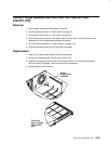
Step 8. Arranging the System Unit and Devices
Note: If you are attaching a 4869 external 5.25-inch diskette drive, do not place it closer
than 155 mm (6 inches) to any display.
If you are attaching a -48V dc power supply, refer to the instructions included in the
-48V dc power cord package.
1. Connect the system unit power cable to the system unit (do not plug it into the outlet at
this time).
2. Arrange the cables at the back of the system unit.
3. Install the rear cover.
4. Using the customer’s planning information, arrange the system unit and devices.
5. Go to Chapter 5 of
7012 300 Series Operator Guide
to check out the system.