


3-20 Installation and Service Guide
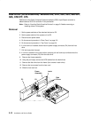
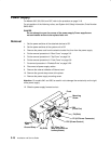
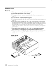
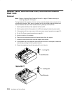
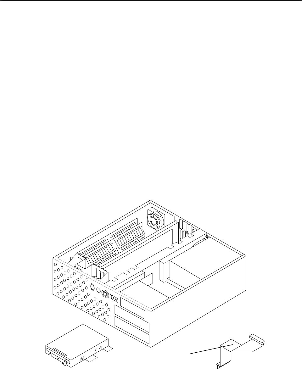
Diskette Drive
Removal
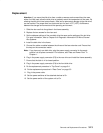
1. Set the power switches of the attached devices to Off.
2. Set the power switches of the system unit to Off.
3. If the system unit model has a rear cover, do the Rear Cover removal procedure on
page 3-3.
4. Do the “Top Cover” removal procedure on page 3-4.
5. For all models, except 380, 390, 39H, and 397, do the Front Cover removal procedure on
page 3-6.
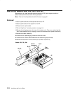
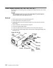
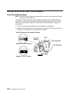
6. If the system unit is a model 380, 390, 39H, or 397, remove the screw on the left side of
the diskette drive plate. If there is also an optional disk drive fan installed, lay it on top of
the power supply. For all other models disconnect the diskette drive cable connector from
the planar (P20) and pull up on the latch.Remove the screw on the left side of the
diskette drive plate. If there is also an optional disk drive fan installed, lay it on top of the
power supply.
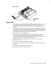
7. If the system unit is a model 380, 390, 39H, or 397, slide the diskette drive assembly
back and lift up; for all other models slide the drive assembly forward and pull up.
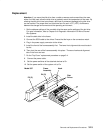
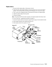
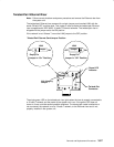
8. If the system unit is a model 380, 390, 39H, or 397, remove the four screws that hold the
diskette drive to the metal plate; for all other models, disconnect the cable from the
diskette drive.
Cable
Models 380, 390,
39H, and 397