


2-1520-8
Installation and Service Guide
Step 13
(from Step 12)
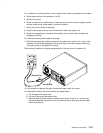
1. Set the power switch on the system unit to Off.
2. Record the slot numbers of the adapters, label and record the location of any cables
attached to the adapters.
3. Remove one of the adapters from the I/O planar. Refer to the “Adapters, Ethernet Riser
Card, External Diskette Riser Card” removal procedure on page 3-24.
4. Set the power switch on the system unit to On. Wait 10 seconds before answering the
following question.
Did the power-on light come on and stay on?
NO Repeat this step until the defective adapter is identified or all the adapters
have been removed.
If the symptom did not change and all the adapters have been removed go
to Step 20.
YES Go to Step 14.
Step 14
(from Step 13)
Look at the adapter that was removed.
Were there any cables attached to the adapter before it was removed?
NO Go to Step 15.
YES Go to Step 17.
Step 15
(from Step 14)
Some adapters may have FRUs on them.
Does the failing adapter have any FRUs?
NO Exchange the failing adapter. Go to “Map 0410: Repair Checkout” in the
Diagnostic Information For Micro Channel Bus Systems
.
YES Go to Step 16.