


Chapter 7. Nortel Networks L2/3 GbESM configuration and network integration 111
Summary of IP Addressing used in this sample
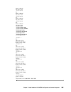
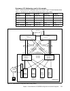
Table 7-1 summarizes the IP addresses used in this sample. Figure 7-6 also illustrates these.
Table 7-1 IP Addresses for Layer 3 Sample Configuration (Static routing, VRRP)
Figure 7-6 Layer 3 sample configuration (static routing, VRRP)
Switch VLAN 35 VLAN 46 VLAN 10 VLAN 20
GbESM 1 10.35.0.243 10.46.0.243 10.10.0.243 10.20.0.243
GbESM 2 10.35.0.244 10.46.0.244 10.10.0.244 10.20.0.244
Core 1 10.35.0.245 none none none
Core 2 none 10.46.0.246 none none
VRRP - GbESMs 10.35.0.100 10.46.0.100 10.10.0.100 10.20.0.100
Core 2
Management
Network
Management
Workstation
BladeCenter
1 2
1
1 2
2
1 2
3
Int1
Int1
Int2
Int2
Int4
1 2
Int3
Int3
Int4
Links between Management Modules and GbESMs not shown
Team
10. 20.0.1 10.10.0.2
10.20.0.2
10.10.0.3
10.20.0.3
10.99.0.4
G0/11
PO1
G0/23
Team
PO2
G0/2
G0/11 G0/12G0/12
G0/1
G0/1 G0/2
PO1
PO2
EXT1 EXT2
EXT1
EXT2
EXT5
EXT6
EXT5
EXT6
EXT3
10.35.0.245
10.46.0.246
10.46.0.0
VLAN 46
10.35.0.0
VLAN 35
GbESM_2
Blade
Server
Blade
Server
Blade
Server
Blade
Server
M
M
1
M
M
2
10.35.0.244
10.46.0.244
10.10.0.244
10.20.0.244
10.35.0.243
10.46.0.243
10.10.0.243
10.20.0.243
VLANS 10, 20
VRRP
10.35.0.100
10.46.0.100
10.10.0.100
10.20.0.100
G0/23
G0/24G0/24
Core 1
4
GbESM_1
9.0.0.0