Chapter 7. Nortel Networks L2/3 GbESM configuration and network integration 125
line vty 5 15
no login
!
!
end
7.8.2 Dynamic routing options OSPF/RIP
This section discusses an enhancement to the Layer 3 configuration that is shown in 7.8.1,
“Layer 3 sample configuration with static routing and VRRP” on page 109. Instead of using
static routes to enable the switches to know how to reach the various subnets, standard
dynamic routing protocols is used. In addition to the use of the dynamic routing protocols, this
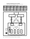
configuration has a slightly different topology than the one above, introducing two additional
VLANs for connections between the GbESMs and the Core switches as well as a direct
cross-connection between the two GbESMs.
The use of these protocols and this more complex topology allows a Layer 3 configuration
which provides High Availability without requiring the use of VRRP. The instructions that
follow assume starting from the configuration that is described in 7.8.1, “Layer 3 sample
configuration with static routing and VRRP” on page 109.
Merits of this configuration
This configuration is robust and suited for environments requiring High Availability. Its
behavior in two key failure modes is:
Switch failure
In the event of a switch failure, the second switch in the BladeCenter chassis will take on
the functions of the failed switch. Upstream (Core1 and Core2 in the samples) switches
updates their routing tables to reflect the absence of the connection to the failed switch
and sends inbound traffic to the second switch. NIC teaming is used to ensure that traffic
is sent by the server blades to the second switch.
Uplink failure
In the event of an uplink failure to the primary switch, upstream (Core1 or Core2) switches
will update their routing tables and send traffic only to the second GbESM.
Outbound traffic will go to the primary switch and then through the crossover link to the
secondary switch unless tracking and hot-standby are used to trigger a VRRP failover.
This sample configuration does not use hot-standby. Instead, it relies on the crossover
connection between the two GbESM modules to forward traffic between the two switches:
the secondary switch, which connects the IBM Eserver BladeCenter to the outside
world, and the primary switch, which continues to forward traffic to and from the server
blades.


