


Chapter 6. IBM Eserver BladeCenter system initial setup 47
Click Save at the bottom of the page. You must restart the Management Module to implement
the changes.
6.1.3 I/O module management tasks
In this section, we set up and configure the Nortel Networks Layer 2/3 Copper Gigabit
Ethernet Switch Module for IBM Eserver BladeCenter.
Nortel Networks L2/3 GbESM setup and configuration
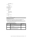
You can install the Nortel Networks L2/3 GbESM into any of the four BladeCenter switch bays
in the rear of the chassis. Bay 1 is attached to one of the Ethernet Network Interfaces
Controllers (NIC) on the blade HS20. Bay 2 is attached to the other Ethernet NIC. Each NIC is
a Gigabit Full Duplex link to only one of the switches. As for HS40, which has a total of four
NICs as standard, each two NICs link to one switch. A switch in bay 3 or bay 4 is required
when a Gigabit Ethernet Expansion Card is being installed on the blade. This card provides
an additional two NICs to the blades. One of the NICs has a dedicated Gigabit Full Duplex
link to bay 3 and the other NIC to bay 4.
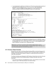
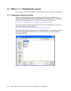
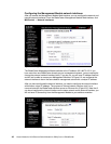
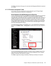
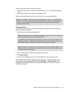
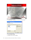
To manage the Nortel Networks L2/3 GbESM in bay 1, from the BladeCenter Management
Module, click I/O Module Tasks → Management. A window similar to the one in Figure 6-4
opens.
Figure 6-4 I/O Module Tasks: Management (Bay 1 Ethernet SM) window
As with the Management Module, the switch must have a unique IP address and be on the
same subnet as the Management Module for out-of-band management. Enter a Gateway
address if attaching to other networks is required.
Click Save to apply these changes immediately. Rebooting or resetting is not required.