


74 Nortel Networks L2/3 Ethernet Switch Module for IBM Eserver BladeCenter
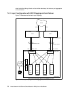
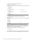
2. Create the VLANs, enable them, and add ports, as shown in
Example 7-5 Create and enable VLANs
/c/l2/vlan 5
ena
name “Native”
def EXT1 EXT2
/c/l2/vlan 10
ena
name "VLAN_Green"
def INT2 INT3 EXT1 EXT2 /* def INT2 EXT1 EXT2
/c/l2/vlan 20
ena
name "VLAN_Red"
def INT1 INT2 EXT1 EXT2 /* def INT1 INT2 INT3 EXT1 EXT2
/c/l2/vlan 99
ena
name "MGMT"
def INT4 EXT1 EXT2
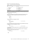
3. In Example 7-6, INT ports must have PVIDs set. Blade servers on INT1, INT3, and INT4
as configured are untagged. The external ports should have PVID set to 5.
Example 7-6 PVIDs set
/c/port EXT1
pvid 5
/c/port EXT2
pvid 5
/c/port INT1
pvid 20
/c/port INT3
pvid 10 /* pvid 20
/c/port INT4
pvid 99
There is one change on GbESM_2 for INT3. This is so that blade server 3, connecting
through INT3, on GbESM_1 will be on VLAN 10. It will be on VLAN 20 through GbESM_2.
INT2 does not need a PVID set on either Nortel because by default it is already set to 1. The
BASP setting for both VL10 and VL20 is set to tagged VLAN.
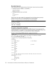
Remove EXT1 and EXT2 from the default VLAN 1 (as a security precaution):
/c/l2/vlan 1
rem EXT1
rem EXT2
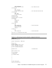
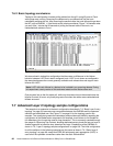
Unlike the Cisco switch, VLAN information is included when dumping the switch configuration
with the /c/d command. VLAN information can be displayed with the /i/l2/vlan command.