


70 Nortel Networks L2/3 Ethernet Switch Module for IBM Eserver BladeCenter
noted is that this offering is basic and has limited redundancy that relies on port aggregation
and trunk failover.
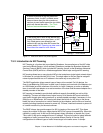
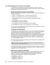
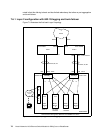
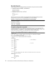
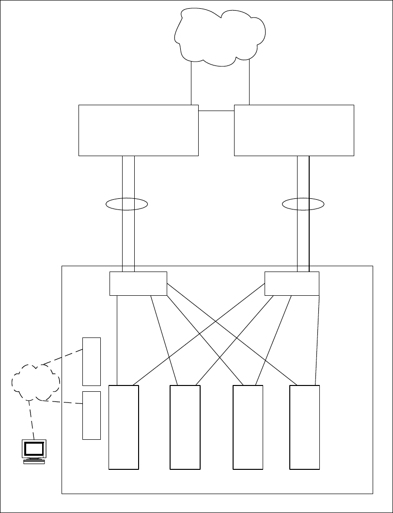
7.6.1 Layer 2 configuration with 802.1Q tagging and trunk failover
Figure 7-3 illustrates the first basic Layer 2 topology.
Figure 7-3 Basic Layer 2 topology with 802.1Q tagging and trunk failover
Core 1
Core 2
G0/23
G0/1
Management
Network
Management
Workstation
G0/2
Ext2
Ext1
GbESM_2GbESM_1
Int1
Int2
Int3
Int4
Links between Management Modules and GbESMs not shown
Ext2
10.99.0.244
G0/1
G0/2
Port Channel
Port Channel
Cisco 3560G G0/23
VLAN 10, 20, 99
VLAN 10, 20, 99
Trunk
Trunk
G0/24 G0/24
BladeCenter
1 2
1
1 2
2
1 2
3
1 2
4
Team
10.20.0.1 10.10.0.2
10.20.0.2
10.10.0.3
10.20.0.3
10.99.0.4
Team
Int1
Int2
Int4
Int3
10.99.0.243
Ext1
M
M
1
M
M
2
Blade
Server
Blade
Server
Blade
Server
Blade
Server
Cisco 3560G
9.0.0.0