


528 COG
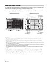
BladeCenter power overview
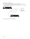
Your BladeCenter unit is separated into two power domains. Power domain A supports all the BladeCenter
modules and bays 1 through 6; power domain A uses power modules 1 and 2.
Power domain B supports bays 7 through 14 and uses power modules 3 and 4. To support devices in power
domain B, a power-supply option (consisting of two power modules) must be installed.
Important:
1. The power modules must be installed in pairs in a domain and must match each other in capacity
(wattage, amperage, and so on).
2. A power domain operating above the capacity of a single power module results in a nonredundant
power condition.
3. In a pair of power modules, a power module that is not connected to 200-240 volt ac power source results
in a nonredundant power condition.
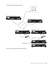
4. To provide true redundant power, BladeCenter power modules 1 and 3 must be connected to a different
200 - 240 volt ac power source than power modules 2 and 4.
5. An installed power module must be connected to an ac power source and must not be used as a filler
module.
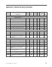
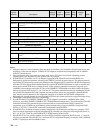
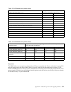
The following tables list the power requirement for each IBM BladeCenter blade server or option that is
available as of the date of this printing. These power requirements assume that each blade server is fully
configured and are based on typical workloads. Use the values in these tables and complete the upgrade
calculation (see “Upgrade calculation” on page 530) to determine which power modules are needed to
deliver full power redundancy for your configuration.
BladeCenter unit front view BladeCenter unit rear view
Power domain A Power domain B
AC
AC
DC
DC
AC
DC
I/O module bay 3
I/O module 1
I/O module bay 4
I/O module 2
Power module 3
Power module 1
Power module 4
Power module 2
Management
module 1
Management
module bay 2
Blower module 1
Blower module 2
AC
DC