86 COG
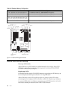
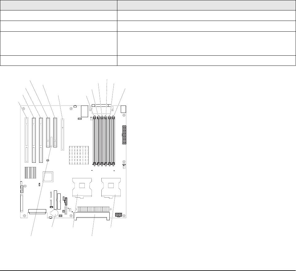
Figure 16. xSeries 226 System Board
xSeries 226 internal cabling
Hot-swap SCSI models
xSeries 226 hot-swap SCSI models are cabled internally with a single, 1-drop LVD
SCSI cable, connecting one channel of the integrated, dual-channel Ultra320 SCSI
controller to the hot-swap backplane.
Simple-swap SATA
All models provide a single ATA-100 IDE connector supporting two IDE devices, one
device being the standard optical cabled via a 2-drop IDE cable.
xSeries 226 simple-swap SATA models provide two point-to-point SATA cables
connecting the two integrated SATA controllers to the SATA simple-swap backplane.
An optional SCSI cable is available to connect the second SCSI channel to the back of
the chassis, enabling an external 0.8mm VHDCI SCSI connector.
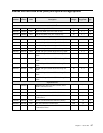
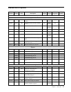
Table 16. Standard Memory Configuration
Model Std. DIMM Configuration
00Y, 0AY, 0BY, 10Y, 1AY, 1BY, 20Y, E3Y 2 x 256MB PC2-3200 ECC DDR2 RDIMM (nonChipkill)
0EY, 4EY, E4Y, E5Y, EFY, EGY 2 x 512MB PC2-3200 ECC DDR2 RDIMM (nonChipkill)
40Y, 4AY, 4BY, 50Y, 5AY, 5BY, 60Y, 6AY, 6BY,
A2Y, A4Y, A6Y, B2Y, B4Y, B6Y, C2Y, C4Y,
C6Y, D2Y, D4Y, D6Y, E2Y, EBY, ECY, EHY
1 x 512MB PC2-3200 ECC DDR2 RDIMM (nonChipkill)
E7Y 4 x 512MB PC2-3200 ECC DDR2 RDIMM (nonChipkill)
Slot 6 PCI-X
Battery
Microprocessor 2
Microprocessor 2VRM
Microprocessor 1
Slot 5 PCI-X
Slot 4 PCI-X
Slot 3 PCI
Slot 2 PCI
Slot 1 PCI
Express x 16
DIMM 5
DIMM 4
DIMM 3
DIMM 2
DIMM 1
DIMM 6
Remote Supervisor
Adapter II


