©2004 Inova Computers GmbH Page A-3ICP-PM/CM Appendix-A
Appendix A
ICP-HD-3
CompactPCI
®
A
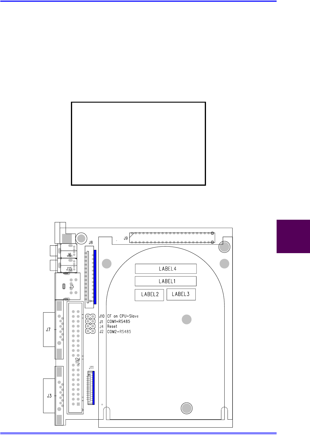
A1.2 IDE Carrier Board ICP-HD-3(-ND)
Figure A1.2 illustrates the construction of the integrated ICP-HD-3 carrier board and the location
of the interface connectors. Table A1.2 gives a description of these interfaces. Care should be
exercised when attaching the LPT interface to this carrier board. Here the connection is via a
length of flex cable between J11 of the carrier and J13 on the LPT module.
Note:
Damage to the CPU, hard-disk carrier
board or the LPT piggyback may
result if the flex cable is positioned
incorrectly. Inova will not accept
responsibility for negligent actions!
Position the blue side of the flex-cable
to the blue-flanked connector shown
below
Figure A1.2 Interface Location of the ICP-HD-3(-ND) Module


