©2004 Inova Computers GmbH Page E-7ICP-P4/PM/CM Appendix-E
Appendix E
AGP-R7000
CompactPCI
®
E
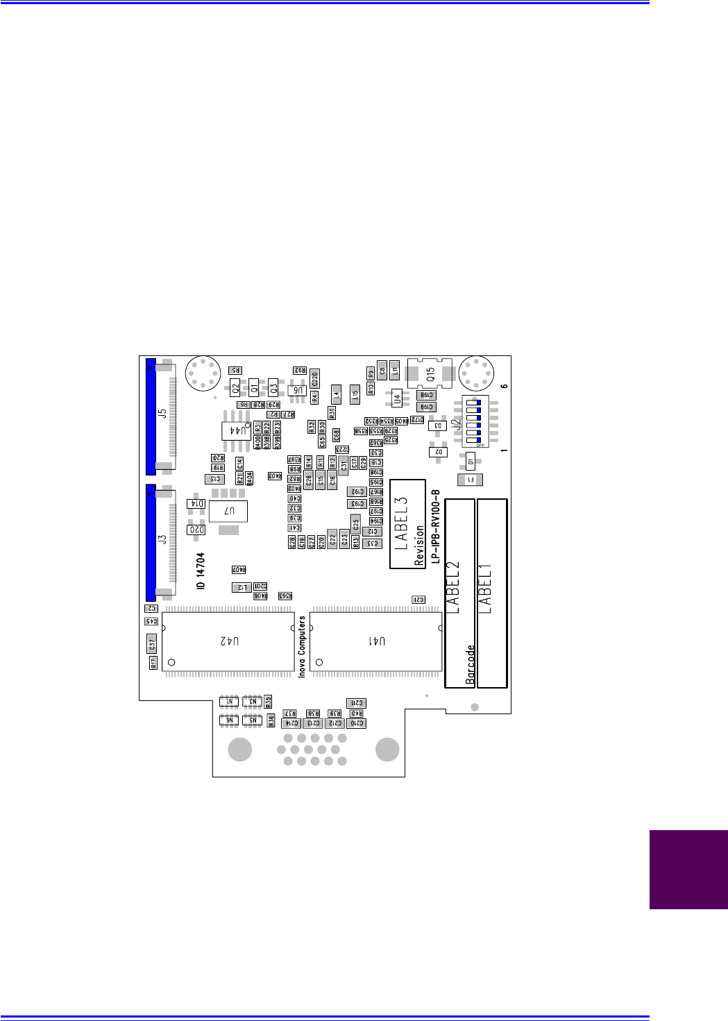
E1.3 J3 & J5 IBP-GS-MULTILINK (TFT) Interfaces
To address an almost unlimited number of cascaded digitally connected (GigaST
Ȣ
R) TFT displays
with optional CAN control and PanelLink Slave connectivity, the Inova GigaST
Ȣ
R transmitter pig-
gyback, IPB-GS-MULTILINK needs to be installed adjacent to the AGP piggyback. This connection
is made through connectors J3 and J5 on the upper side of the piggyback as shown in figure
E1.30. Table E1.30 gives the pinout of these two connectors.
The settings of the DIP switch (J2) are explained later.
Figure E1.30 J3 and J5 Topside Connectors for the Inova IPB-GS-MULTILINK
Also visible on the upper side of this piggyback are three labels - one (Label 1) shows the name of
the board, the second shows the product bar code (with manufacturing details, lot number and
ID number) and the third (Label 3) carries the revision number. The board revision is also printed
on the PCB.


