©2004 Inova Computers GmbHPage C-10 ICP-P4/PM/CM Appendix-C
ITM-RIO
Appendix C
C1.8 Fast Ethernet Interface
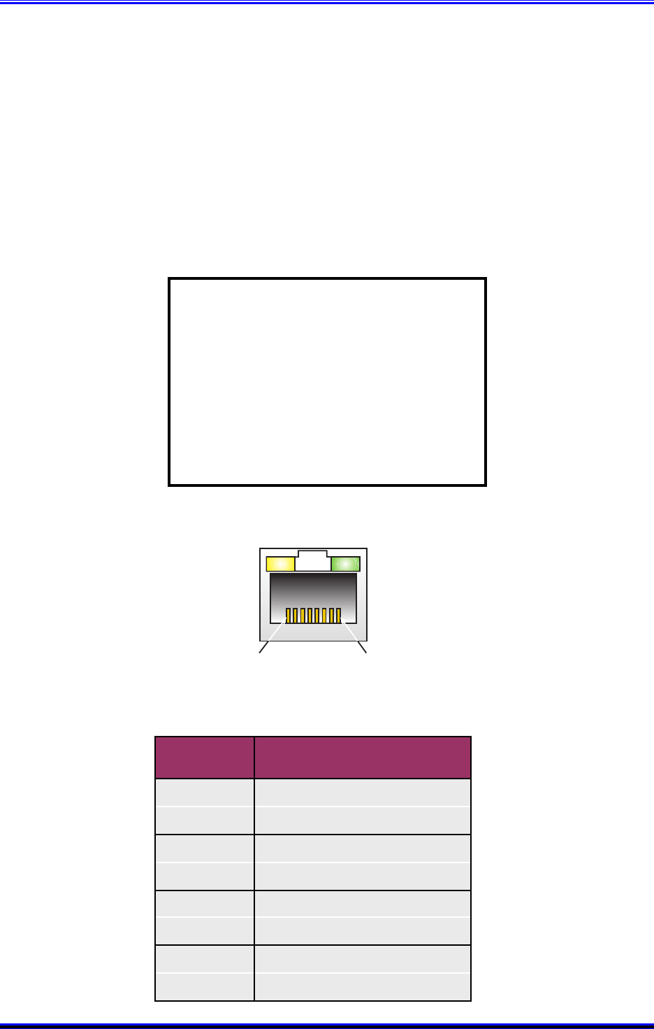
Standard to all rear I/O (D) transition modules is the Fast Ethernet connection. Figure C1.8 and
Table C1.8 provide the pinout and signal description of this standard Ethernet interface respec-
tively. Although the LEDs feature on the Ethernet connector, these are not physically connected to
the rear I/O interface board. Instead, if this interface is used, communication traffic can still be
observed on the front-panel Ethernet connector!
Note:
The single channel Fast Ethernet
option in table C1.10 is either ETH 1
or ETH 2 on the front-panel depending
on the computer platform. If the rear
I/O option is used then the front-panel
connection using the same controller
must not be used. Doing so will
disrupt the communication leading to
spurious results.
Figure C1.8 Fast Ethernet Interface Pinout
81
Table C1.8 Fast Ethernet Connector Signals
Pin No.
Signal Description
Ethernet / Fast Ethernet
1 TX0+
2 TX0-
3 RX0+
4
5
6 RX0-
7
8


