


32 Intel® 41110 Serial to Parallel PCI Bridge Design Guide
PCI-X Layout Guidelines
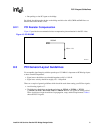
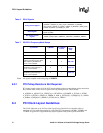
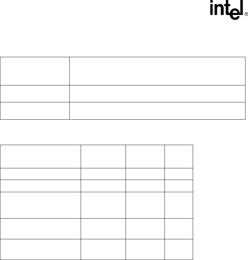
Table 7. PCI/PCI-X Frequency/Mode Straps
Note: All signals sampled on the rising edge of PERST#.
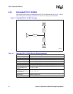
8.3.1 PCI Pullup Resistors Not Required
PCI control signals on the 41110 do NOT require pullup resistors on the adapter card to ensure that
they contain stable values when no agent is actively driving the bus. These include:
A_ACK64#, A_AD[63:32], A_CBE#[7:4], A_DEVSEL#, A_FRAME#, A_INTA#, A_INTB#,
A_INTC#, A_INTD#, A_IRDY#, A_PERR#, A_PAR, A_GNT#[5:0], A_REQ#[5:0], A_LOCK#,
A_PAR64, A_REQ64#, A_SERR#, A_STOP#, and A_TRDY#
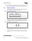
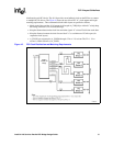
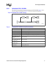
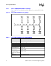
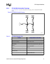
8.4 PCI Clock Layout Guidelines
The PCI-X Addendum to the PCI Local Bus Specification, Revision 1.0a compliant, allows a
maximum of 0.5 ns clock skew timing for each of the PCI-X frequencies: 66 MHz, 100 MHz and
133 MHz. A typical PCI-X application may require separate clock point-to-point connections
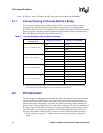
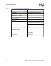
Table 6. PCI-X Signals
Timing Critical Signals
A PCI Bus Segment:
A_ACK64#, A_AD[63:0], A_CBE_[7:0]#, A_DEVSEL#, A_FRAME#,
A_GNT_[5:0]#, A_IRDY#, A_LOCK#, A_PAR64, A_REQ64#, A_REQ_[5:0]#,
A_STOP#, A_TRDY#, A_CLKO[6:0], A_CLKI
Reset Signals
A PCI Bus Segment:
A_RST#, A_PME#
Non Timing Critical
Signals
A PCI Bus Segment:
A_133EN, A_IRQ[15:0]#, A_M66EN, A_PCIXCAP, A_PERR#, A_SERR#
A_PCIXCAP A_M66EN A_133EN(on
board)
Bus
Mode/
Freq
00XPCI 33
01XPCI 66
PCI-X 66MHz cards connect this
signal to ground through a 10KΩ
±5% resistor in parallel with a
0.01uF ±10% capacitor.
XXPCI-X 66
PCI-X 133 MHz cards connect
PCIXCAP to ground through a
0.01uF ±10% capacitor.
X0PCI-X 100
PCI-X 133 MHz cards connect
PCIXCAP to ground through a
0.01uF ±10% capacitor.
X1PCI-X 133