Signal Descriptions
150 Intel® Xeon® Processor E5-1600/E5-2600/E5-4600 Product Families
Datasheet Volume One
6.10 Processor Power and Ground Supplies
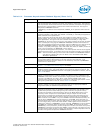
TXT_AGENT Intel TXT Platform Enable Strap.
0 = Default. The socket is not the Intel TXT Agent.
1 = The socket is the Intel TXT Agent.
In non-Scalable DP platforms, the legacy socket (identified by SOCKET_ID[1:0] = 00b)
with Intel TXT Agent should always set the TXT_AGENT to 1b.
On Scalable DP platforms the Intel TXT AGENT is at the Node Controller.
Refer to the Platform Design Guide for more details.
This signal is pulled down on the die, refer to Table 7-6 for details.
TXT_PLTEN Intel TXT Platform Enable Strap.
0 = The platform is not Intel TXT enabled. All sockets should be set to zero. Scalable DP
(sDP) platforms should choose this setting if the Node Controller does not support Intel
TXT.
1 = Default. The platform is Intel TXT enabled. All sockets should be set to one. In a non-
Scalable DP platform this is the default. When this is set, Intel TXT functionality requires
user to explicitly enable Intel TXT via BIOS setup.
This signal is pulled up on the die, refer to Table 7-6 for details.
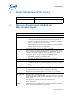
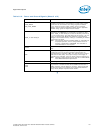
Table 6-15. Miscellaneous Signals
Signal Name Description
IVT_ID_N This output can be used by the platform to determine if the installed processor is a
future processor planned for the Intel® Xeon® processor E5-1600/E5-2600/E5-4600
product families-based Platform. There is no connection to the processor silicon for this
signal. This signal is also used by the VCCPLL and VTT rails to switch their output voltage
to support future processors.
SKTOCC_N SKTOCC_N (Socket occupied) is used to indicate that a processor is present. This is
pulled to ground on the processor package; there is no connection to the processor
silicon for this signal.
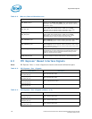
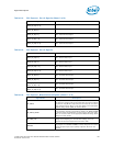
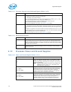
Table 6-16. Power and Ground Signals (Sheet 1 of 2)
Signal Name Description
VCC
Variable power supply for the processor cores, lowest level caches
(LLC), ring interface, and home agent. It is provided by a VRM/
EVRD 12.0 compliant regulator for each CPU socket. The output
voltage of this supply is selected by the processor, using the serial
voltage ID (SVID) bus.
Note: VCC has a Vboot setting of 0.0V and is not included in the
PWRGOOD indication. Refer to the
VR12/IMVP7 Pulse
Width Modulation Specification
.
VCC_SENSE
VSS_VCC_SENSE
VCC_SENSE and VSS_VCC_SENSE provide an isolated, low
impedance connection to the processor core power and ground.
These signals must be connected to the voltage regulator feedback
circuit, which insures the output voltage (that is, processor
voltage) remains within specification. Please see the applicable
platform design guide for implementation details.
VSA_SENSE
VSS_VSA_SENSE
VSA_SENSE and VSS_VSA_SENSE provide an isolated, low
impedance connection to the processor system agent (VSA) power
plane. These signals must be connected to the voltage regulator
feedback circuit, which insures the output voltage (that is,
processor voltage) remains within specification. Please see the
applicable platform design guide for implementation details.
Table 6-14. Processor Asynchronous Sideband Signals (Sheet 3 of 3)
Signal Name Description


