Electrical Specifications
166 Intel® Xeon® Processor E5-1600/E5-2600/E5-4600 Product Families
Datasheet Volume One
Technology transitions signal. Please refer to the Intel® 64 and IA-32 Architectures
Software Developer’s Manual (SDM) Volumes 1, 2, and 3
for details on the FLEX_RATIO
MSR and setting the processor core frequency.
Not all operating systems can support dual processors with mixed frequencies. Mixing
processors of different steppings but the same model (as per CPUID instruction) is
supported provided there is no more than one stepping delta between the processors,
for example, S and S+1.
S and S+1 is defined as mixing of two CPU steppings in the same platform where one
CPU is S (stepping) = CPUID.(EAX=01h):EAX[3:0], and the other is S+1 =
CPUID.(EAX=01h):EAX[3:0]+1. The stepping ID is found in EAX[3:0] after executing
the CPUID instruction with Function 01h.
Details regarding the CPUID instruction are provided in the
AP-485, Intel® Processor
Identification and the CPUID Instruction application note. Also refer to the Intel®
Xeon® Processor E5 Prodcut Family Specification Update
.
7.6 Flexible Motherboard Guidelines (FMB)
The Flexible Motherboard (FMB) guidelines are estimates of the maximum values the
processor will have over certain time periods. The values are only estimates and actual
specifications for future processors may differ. Processors may or may not have
specifications equal to the FMB value in the foreseeable future. System designers
should meet the FMB values to ensure their systems will be compatible with future
processors.
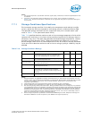
7.7 Absolute Maximum and Minimum Ratings
Table 7-9 specifies absolute maximum and minimum ratings. At conditions outside
functional operation condition limits, but within absolute maximum and minimum
ratings, neither functionality nor long-term reliability can be expected. If a device is
returned to conditions within functional operation limits after having been subjected to
conditions outside these limits, but within the absolute maximum and minimum
ratings, the device may be functional, but with its lifetime degraded depending on
exposure to conditions exceeding the functional operation condition limits.
Although the processor contains protective circuitry to resist damage from Electro-
Static Discharge (ESD), precautions should always be taken to avoid high static
voltages or electric fields.
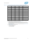
Table 7-9. Processor Absolute Minimum and Maximum Ratings
Symbol Parameter Min Max Unit
V
CC
Processor core voltage with respect to Vss -0.3 1.4 V
V
CCPLL
Processor PLL voltage with respect to Vss -0.3 2.0 V
V
CCD
Processor IO supply voltage for DDR3
(standard voltage) with respect to V
SS
-0.3 1.85 V
V
CCD
Processor IO supply voltage for DDR3L (low
Voltage) with respect to V
SS
-0.3 1.7 V
V
SA
Processor SA voltage with respect to V
SS
-0.3 1.4 V
V
TTA
V
TTD
Processor analog IO voltage with respect to
V
SS
-0.3 1.4 V


