


9
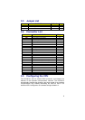
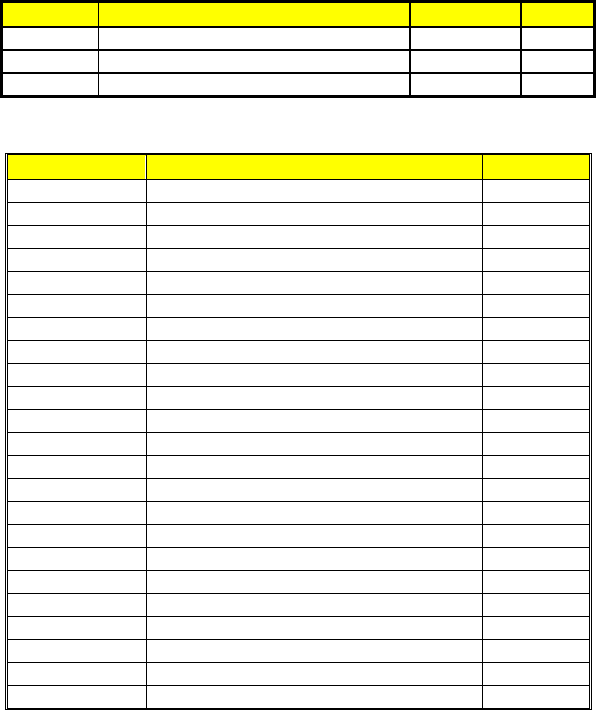
3.3 Jumper List
Jumper Definition Default Page
JP1 Watchdog Timer Active Type Select Short 2-3 20
JP2 Panel Voltage Select Short 1-2 12
JP4 Clear CMOS Short 1-2 18
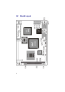
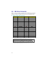
3.4 Connector List
Connector Definition Page
JP3 Reset Button 20
CN1 4-pin Power In Connector 18
CN2 PC/104 64-pin Connector 26
CN3
PC104 40-pin Connector 25
CN4 RJ45 and LAN LED Connector 17
CN5 2-pin Power In Connector 18
CN6 CRT Connector 12
CN7 PS/2 6-pin Mini Din KB/Mouse Connector 19
CN8 6-pin Keyboard/Mouse Connector 19
CN9 IrDA Connector 17
CN10 Panel Connector 13
CN11 Floppy Connector 15
CN12 IDE Connector 14
CN13 USB Connector 18
CN14 COM2 Connector (5x2 Header) 16
CN15
COM1 Connector (5x2 Header) 16
CN16 Parallel Connector 16
CN17 CompactFlash Connector 22
LD1 Power LED Connector 19
LD2 HDD LED Connector 19
PC1 Mini PCI Connector 23
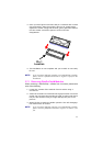
U2 SO-DIMM Socket 10
U7 DiskOnChip Socket 10
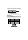
3.5 Configuring the CPU
The HS-2601A, with its onboard BGA processor, auto-detects the
features of the mounted microprocessor onboard. The HS-2601A
automatically identifies the frequency and clock speed of the installed
microprocessor chip, thereby eliminating the need for user to do
additional CPU configuration or hardware settings related to it.