


18
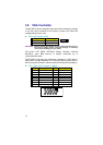
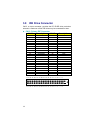
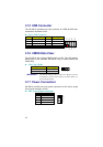
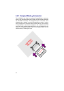
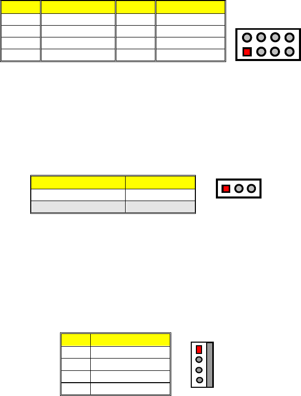
3.15 USB Connector
The HS-2601A provides one 8-pin connector for USB0 & USB1 port
connections at location CN13.
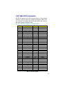
CN13: USB Connector
PIN Description PIN Description
1 VCC 2 VCC
3 BD0- 4 BD1-
5 BD0+ 6 BD1+
7 GND 8 GND
1
2
7
8
VCC
BD1-
BD1+
GND
VCC
BD0-
BD0+
GND
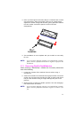
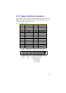
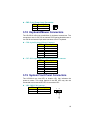
3.16 CMOS Data Clear
The HS-2601A has a Clear CMOS jumper on JP4. The JP4 settings
below apply to the standard HS-2601A using a battery backed up
CMOS chip.
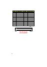
JP4: Clear CMOS
Options Settings
Normal Operation Short 1-2
* Clear CMOS Short 2-3
1 23
IMPORTANT:
The default setting of JP4 is Short 2-3. Before you turn
on the power of your system, please set JP4 to Short 1-2
for normal operation.
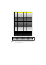
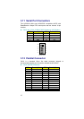
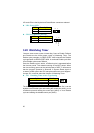
3.17 Power Connectors
HS-2601A provides one 4-pin power connector at CN1 and a single
2-pin power connector at CN5.
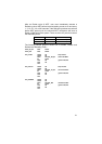
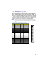
CN1: 4-pin Power Connector
PIN Description
1 VCC
2 GND
3 GND
4 +12V
1
4
VCC
GND
GND
+12V