


Table of Contents
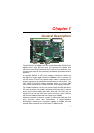
Chapter 1 General Description ---------------------------------6
1.1
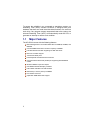
Major Features ------------------------------------------------------2
1.2
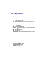
Specifications -------------------------------------------------------3
1.3
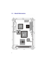
Board Dimensions -------------------------------------------------4
Chapter 2 Unpacking ---------------------------------------------5
2.1
Opening the Delivery Package---------------------------------5
2.2
Inspection-------------------------------------------------------------5
Chapter 3 Hardware Installation-------------------------------7
3.1
Before Installation--------------------------------------------------7
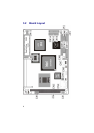
3.2
Board Layout --------------------------------------------------------8
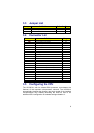
3.3
Jumper List-----------------------------------------------------------9
3.4
Connector List ------------------------------------------------------9
3.5
Configuring the CPU ----------------------------------------------9
3.6
System Memory--------------------------------------------------- 10
3.7
DiskOnChip
Address Setting ------------------------------ 10
3.7.1
Installing DiskOnChip
Modules-------------------------------10
3.7.1
Removing DiskOnChip
Modules -------------------------------11
3.8
VGA Controller---------------------------------------------------- 12
JP2: Panel Voltage Select--------------------------12
CN6: 15-pin CRT Connector (DB15) ---------------12
CN10: 50-pin Panel Connector --------------------13
3.9
IDE Drive Connector--------------------------------------------- 14
CN12: Primary IDE Connector ---------------------14
3.10
Floppy Disk Drive Connector--------------------------------- 15
CN11: FDD Connector------------------------------15
3.11
Serial Port Connectors ----------------------------------------- 16
CN15 and CN14: COM1/COM2 Connector
(5x2 Header)----------------------------------------16
3.12
Parallel Connector ----------------------------------------------- 16
CN16: Parallel Connector--------------------------16
3.13
Ethernet Connector---------------------------------------------- 17
CN4: RJ-45 and LAN LED Connector --------------17
3.14
IrDA Connector --------------------------------------------------- 17
CN9: IrDA Connector-------------------------------17
3.15
USB Connector --------------------------------------------------- 18
CN13: USB Connector ------------------------------18
3.16
CMOS Data Clear------------------------------------------------- 18
JP4: Clear CMOS------------------------------------18