


20
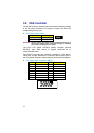
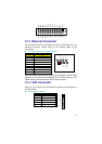
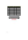
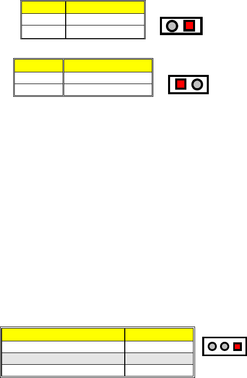
LD1 and JP3 are the Keylock and Reset Button connectors onboard.
LD1: Power LED
PIN Description
1
+5V
2 GND
12
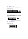
JP3: Reset Button Connector
PIN Description
1
GND
2 External Reset
12
GND
Ext. Reset
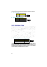
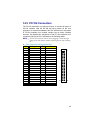
3.20 Watchdog Timer
There are three access cycles of Watch-Dog Timer as Enable, Refresh
and Disable are the three access cycles of Watchdog Timer. The
Enable cycle proceeds via READ PORT 443H whereas the Disable
cycle proceeds via READ PORT 045H. A continued Enable cycle after
a first Enable cycle means Refresh.
Once the Enable cycle is active, a Refresh cycle is requested before
the time-out period. This restarts counting of the WDT period. When
the time counting goes over the period preset of WDT, it will assume
that the program operation is abnormal. A System Reset signal to
re-start or a NMI cycle to the CPU transpires when such error happens.
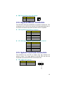
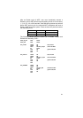
Jumper JP1 is used to select the function of Watchdog Timer.
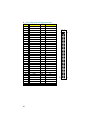
JP1
:
Watchdog Timer Active Type Setting
Options Settings
Active NMI Short 1-2
System Reset (default) Short 2-3
Disabled Watchdog Timer Open
123
The Watchdog Timer is disabled after the system Power-On. It can be
enabled via an Enable cycle and reading the control port (443H), or via
a Refresh cycle and reading the control port (443H), or via a Disable
cycle and reading the disable control port (045H).