


Server Board Installation and Upgrades 47
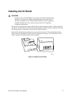
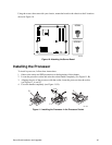
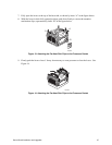
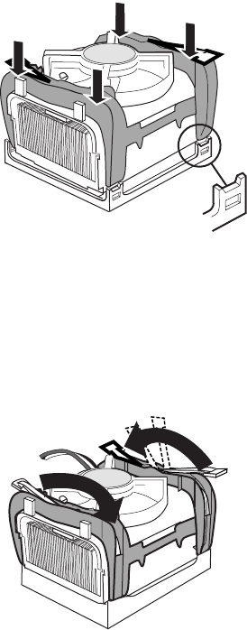
7. Fully open the levers at the top of the heat sink, as shown by letter “A” in the figure below.
8. With the levers in their fully opened position, push down firmly to secure the retention
mechanism clips, represented by letter “B” in the figure below.
TP00209
A
B
A
Figure 13. Attaching the Fan Heat Sink Clips to the Processor Socket
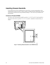
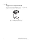
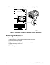
9. Firmly push the levers closed. It may be necessary to exert pressure to close the levers. See
Figure 14.
TP00206
Figure 14. Attaching the Fan Heat Sink Clips to the Processor Socket