


Server Board Installation and Upgrades 55
Connecting Internal Headers
Before connecting internal headers, observe the precautions in “Before You Begin” on page 39.
TP00194
1 2
33 34
19
210
A
B
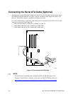
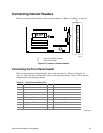
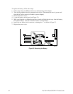
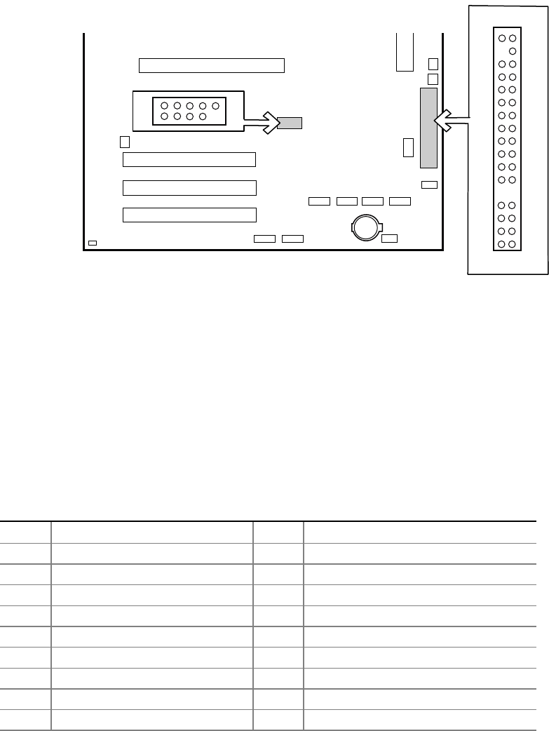
A Front Panel USB 2.0 Header
B Front Panel Header
Figure 20. Location of Internal Headers
Connecting the Front Panel Header
Before connecting the front panel header, observe the precautions in “Before You Begin” on
page 39. Figure 20 (above) shows the location of the front panel header. Table 12 shows the pin
assignments for the front panel header.
Table 12. Front Panel Header (J7J1)
Pin Signal Name Pin(s) Function
1 Power LED Anode 2 5VSB
3 Key 4 Unused
5 GND 6 Unused
7 HDD Activity LED Anode 8 Unused
9 HDD Activity LED Cathode 10 Unused
11 Power Switch 12 NIC#1 Activity LED Anode
13 GND (Power Switch) 14 NIC#1 Activity LED Cathode
15 FP_RST* 16 I1C SDA
17 GND (Reset Switch) 18 I2C SDA
continued