


Contents vii
Figures
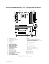
Figure 1. Server Board Components ..........................................................................................11
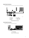
Figure 2. Back Panel Connectors ...............................................................................................12
Figure 3. Front Panel Connectors...............................................................................................12
Figure 4. Location of the Standby Power Indicator LED CR7J1.................................................29
Figure 5. Location of Clear CMOS Jumper.................................................................................32
Figure 6. Installing the I/O Shield................................................................................................41
Figure 7. Installing Chassis Standoffs in the SC5200 Chassis...................................................42
Figure 8. Installing Chassis Standoffs in the SC5250-E Chassis ...............................................43
Figure 9. Placing the Server Board into the Chassis ..................................................................44
Figure 10. Attaching the Server Board........................................................................................45
Figure 11. Installing the Processor in the Processor Socket ......................................................45
Figure 12. Attaching the Heat Sink to the Processor..................................................................46
Figure 13. Attaching the Fan Heat Sink Clips to the Processor Socket......................................47
Figure 14. Attaching the Fan Heat Sink Clips to the Processor Socket......................................47
Figure 15. Connecting the Processor Fan Cable to the Processor Fan Connector....................48
Figure 16. DIMM Socket Locations.............................................................................................50
Figure 17. Installing the AGP Card .............................................................................................52
Figure 18. Connecting the IDE Cable .........................................................................................53
Figure 19. Connecting the SATA Cable......................................................................................54
Figure 20. Location of Internal Headers......................................................................................55
Figure 21. Location of the Fan Headers and Power Connectors................................................57
Figure 22. BIOS Configuration Jumper Block Location ..............................................................58
Figure 23. Removing the Battery ................................................................................................62
Figure 24. Power, Fan, and Chassis Intrusion Connectors.......................................................102
Figure 25. Add-in Board and Peripheral Interface Connectors.................................................103
Tables
Table 1. Server Board Features ....................................................................................9
Table 2. Supported Processors...................................................................................13
Table 3. Video Modes..................................................................................................16
Table 4. PCI Bus Characteristics.................................................................................20
Table 5. PCI Bus Configuration IDs.............................................................................21
Table 6. 10/100 Ethernet LAN Connector LEDs..........................................................23
Table 7. 10/100/1000 Gigabit Ethernet LAN Connector LEDs ....................................24
Table 8. Effects of Pressing the Power Switch under ACPI ........................................25
Table 9. Wake-up Devices and Events .......................................................................26
Table 10. Fan Connector Function/Operation ...............................................................28
Table 11. Supervisor and User Password Functions ....................................................31
Table 12. Front Panel Header (J7J1) ............................................................................55
Table 13. USB 2.0 Header (J7E1).................................................................................56
Table 14. Jumper Settings for the BIOS Setup Program Modes (J8J2)........................59
Table 15. BIOS Setup Program Menu Bar ....................................................................68
Table 16. BIOS Setup Program Function Keys.............................................................69
Table 17. Maintenance Menu........................................................................................69
Table 18. Main Menu.....................................................................................................70
Table 19. Advanced Menu.............................................................................................71
Table 20. PCI Configuration Submenu..........................................................................72