10 Intel Server Board SE7500CW2 Product Guide
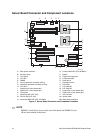
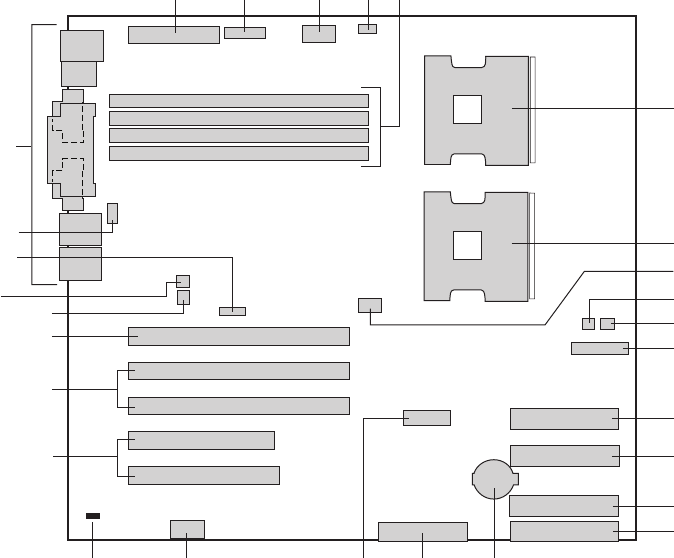
Server Board Connector and Component Locations
OM14279A
BB
Z
DIMM Memory Connector 2B
DIMM Memory Connector 3B
DIMM Memory Connector 3A
DIMM Memory Connector 2A
USB
Main Power
Aux. Pwr
W
V
S
T
U
Q
P
N
L
K
I
H
G
F
DE
C
A
X
B
J
M
O
Y
R
AA
A. Main power connector
B. Auxiliary signal
C. CPU power
D. CPU fan 1
E. DIMMs
F. Primary processor connector (CPU1)
G. Secondary processor connector (CPU2)
H. CPU fan 2
I. System fan 2 (front chassis fan)
J. System fan 1 (front chassis fan)
K. Front panel
L. Secondary IDE (ATA 100)
M. Primary IDE (ATA 100)
N. Secondary RAID IDE (ATA 100 RAID)
O. Primary RAID IDE (ATA 100 RAID)
P. Battery
Q. Floppy drive connector
R. Front panel USB
S. Serial port 2
T. Chassis Intrusion
U. PCI 32/33
V. PCI-X 64/100
W. PCI-X 64/133
X. System fan 4 (rear chassis fan)
Y. System fan 3 (rear chassis fan)
Z. I2C connector
AA. Jumper block
BB. Back panel connectors
Figure 2. Server Board Connector and Component Locations
✏
NOTE
DIMMs 1A and 1B are closest to the side of the board and DIMMs 2A and
2B are in the middle of the board.


