


102
Appendix B
VMEbus Connectors
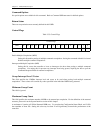
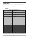
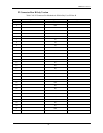
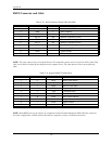
The following tables show the pin numbers and signal description for the P1 and P2 VMEbus Connectors.
• Table C-39 - P1 Connector Signal Descriptions (All Versions)
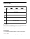
• Table C-40 - P2 Connector For Motherboards Which Only Uses P2 Row B
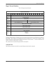
P1 Connector
Table C-39. P1 Connector Signal Descriptions (All Versions)
PIN Row A Signal Mnemonic Row B Signal Mnemonic Row C Signal Mnemonic
1 D00 BBSY* D08
2 D01 BCLR* D09
3 D02 ACFAIL* D10
4 D03 BG0IN* D11
5 D04 BG0OUT* D12
6 D05 BG1IN* D13
7 D06 BG1OUT* D14
8 D07 BG2IN* D15
9 GND BG2OUT* GND
10 SYSCLK BG3IN* SYSFAIL*
11 GND BG3OUT* BERR*
12 DS1* BR0* SYSRESET*
13 DS0* BR1* LWORD*
14 WRITE BR2* AM5
15 GND BR3* A23
16 DTACK AM0 A22
17 GND AM1 A21
18 AS* AM3 A20
19 GND AM3 A19
20 IACK GND A18
21 IACKIN* A17
22 IACKOUT* A16
23 AM4 GND A15
24 A07 IRQ7* A14
25 A06 IRQ6* A13
26 A05 IRQ5* A12
27 A04 IRQ4* A11
28 A03 IRQ3* A10
29 A02 IRQ2* A09
30 A01 IRQ1* A08
31 -12V DC +12V DC
32 +5V DC +5V DC +5V DC