


VMEbus Short I/O Interface
5
VMEbus Short I/O Interface
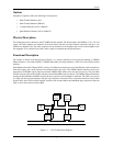
The VMEbus Short I/O interface allows for VMEbus host and onboard CPU communications. The host issues
commands to the Condor through the Short I/O interface and the CPU issues status back to the host.
The Short I/O Interface is a Slave-only interface to the Condor and contains two independent, jumper-configurable,
slave-access areas. The areas can be configured to be 256, 512-, 1K- or 2K- bytes in length.
VMEbus address lines A(15-08) and the Address Modifier lines are compared with the jumper-configurable,
slave-access areas. Address Modifiers "2D" and "29" are supported for the Short I/O access.
The Short I/O Mailboxes physically reside in the CPU Core SRAM. The reset and mailbox location monitor logic
resides in the VMEbus Short I/O Interface.
CPU Core
The CPU (and core logic) controls and configures the rest of the Condor. Each of the commands issued to the FECs
and the VMEbus DMA engine are issued by the onboard CPU.
The CPU Core consists of a MC68EC030 CPU and associated support logic. The CPU Core support logic includes the
following:
• EPROM/FLASH
• Serial EPROM
• SRAM
• DUART Port
• Address Decoder
• Wait State Generator
• STERM/DSACK Generator
• Control/Status Registers
• Hardware Strobes
• Clock Generation
• Interrupt Handler
• FLASH ROM Hardware
The program for the CPU is stored in a single-byte-wide, EPROM (or FLASH) device. The EPROM can be 128K-,
256K- or 512K- bytes in size. There are two SRAM banks which consists of four SRAM devices for each bank. The
two banks of SRAM combined provide for 128K-, 256K, 512K- and 1M-byte of SRAM. At board power-up, the
program is copied from the EPROM (or FLASH) device to the SRAM banks. The program is then executed from the
higher performance SRAM devices.
The interrupt-handler logic combines the three level interrupt from the DMA engine and the non-DMA
engine-interrupt sources and outputs the three-level interrupt signals to the CPU. During CPU IACK cycles, the