


Chapter 2 - Hardware Installation
14
4221 Condor Hardware Installation Procedures
For proper installation of the Condor, it is imperative that you use the following procedures.
Step 1. Visual Inspection
Before attempting the installation of this board, make sure you are wearing an anti-static or grounding device. Remove
the Condor board from the anti-static bag, and visually inspect it to ensure no damage has occurred during shipment.
A visual inspection usually is sufficient, since each board is thoroughly checked at Interphase just prior to shipment.
If the board is undamaged and all parts are accounted for, proceed with the installation.
Step 2. Fuse And Diagnostic LEDs
The following discusses the fuse, diagnostic LEDs, and board status LEDs.
Fuse
The AUI version of the Condor has a 1.5A fuse (F1) used to protect the +12 volts when provided by the
Condor. Its part number is LITTLEFUSE 273-01.5. To determine the location of the fuse on the board, refer
to the appropriate board layout.
Diagnostic LEDs
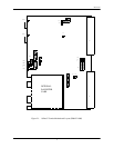
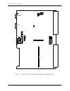
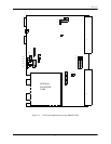
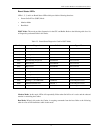
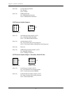
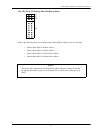
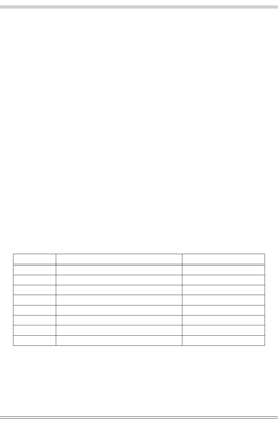
The Condor has as many as 8 LEDs that are mounted on the component side of the motherboard. Refer to
Figures 2-1 and 2-2 for illustrations that shows the location of the component side LEDs. The following table
lists all LEDs and states their function and location.
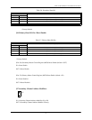
Table 2-2. 4221 Condor LEDs
Designator Description Location
LED 1 Board Status 0 (LSB) Component Side
LED 2 Board Status 1 Component Side
LED 3 Board Status 2 Component Side
LED 4 Board Status 3 (MSB) Component Side
LED 5 Board OK (Red/Green) Green = Board OK Component Side
LED 6 Fused +12 Volts Status (AUI only) Component Side
LED 7 FEC1, Link OK Status (10BaseT only) Component Side
LED 8 FEC0, Link OK Status (10BaseT only) Component Side