


4221 Condor Hardware Installation Procedures
15
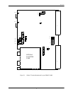
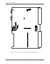
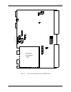
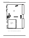
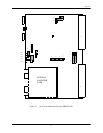
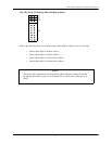
Board Status LEDs
LEDs 1, 2, 3, and 4 are Board Status LEDs which provide the following functions:
• Power On Self Test (POST) Mode
• Monitor Mode
• Run Mode
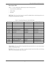
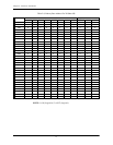
POST Mode: This mode provides diagnostics for the CPU and Buffer. Refer to the following table for a list
of diagnostics performed while in this mode:
Table 2-3. Board Status Diagnostics Used In POST Mode
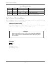
Monitor Mode: In this mode, LEDs will sequentially flicker when Serial Port A is active and the onboard
monitor is controlling the Condor.
Run Mode: When in this mode, the Condor is accepting commands from the host. Refer to the following
table for a list of LED definitions while in this mode:
Hex Code Diagnostic Definition Type of Test
0x01 CPU Register Test CPUFAIL CPU Core Test
0x02 ROM Checksum ROMFAIL CPU Core Test
0x03 Walking 1’s SRAM STAT1FAIL CPU Core Test
0x04 Walking 0’s SRAM STAT0FAIL CPU Core Test
0x05 Decrementing Longwords STATLFAIL CPU Core Test
0x06 Word Access STATWFAIL CPU Core Test
0x07 Byte Access STATBFAIL CPU Core Test
0x08 Reserved RESERVED CPU Core Test
0x09 Walking 1’s In Buffer BUFFERFAIL1 Static Buffer Test
0x0A Walking 0’s In Buffer BUFFERFAIL0 Static Buffer Test
0x0B Decrementing Longwords BUFFERFAIL Static Buffer Test
0x0C Walking 1’s, 0’s VME DMA VMEFAIL Control Register Access
0x0D Motherboard FEC Tests FEC0 & 1 Control Register Access
0x0E Daughter Card FEC Tests FEC2 & 3 Control Register Access