


105
Ethernet Connectors and Pinouts
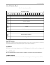
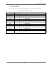
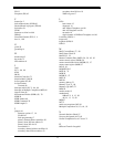
AUI Connector Signals
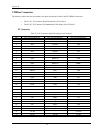
The AUI signals and connector pinout for the DB15 connector are shown in the following table.
Table C-42. DB15 (AUI) Connector Signals
Symbol
Dir Pin Description
GND - 1 Digital Ground
CLSNx I 2 Collision
TRMTx O 3 Transmit
GND - 4 Digital Ground
RCVx I 5 Receive Data
GND - 6 Positive 12 Volts Return
- - 7 No Connection
GND - 8 Digital Ground
CLSNx* I 9 Collision Inverted
TRMTx* O 10 Transmit Inverted
GND - 11 Digital Ground
RCVx* I 12 Receive Inverted
12VDC - 13 Positive 12 Volts
GND - 14 Digital Ground
- - 15 No Connection