


System Interface
55
System Interface
This section defines how the host communicates with the controller. The shared memory interface is defined, and each
major section described in detail. Full definitions for particular commands (what is communicated) can be found in
a following section.
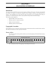
MACSI Organization
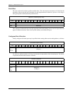
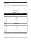
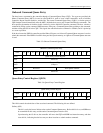
Ethernet MACSI for the Condor consists of eight major sections, as illustrated in the following memory map:
Table 3-1. MACSI Memory Map
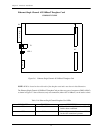
The Master Control/Status Block (MCSB) is used to pass and receive information relating to the overall functioning of
the controller.
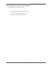
MACSI Memory Map
Addr 1514131211109876543210
0x000
to
0x00F
Master Control Status Block
(16 Bytes)
0x010
to
0x01B
Master Command Queue Entry
(12 Bytes)
0x01C
to
0xXXX
Command Queue Entries
(12 Bytes * N)
0xXXX
to
0x72F
Onboard IOPBs (optional)
(1812 - 12N Bytes)
0x730
to
0x73F
Command Response Block
(16 Bytes)
0x740
to
0x763
Returned IOPB / Multiple Completion Return
(36 Bytes)
0x764
to
0x7AB
Configuration Status Block / Multiple Completion Return
(72 Bytes)
0x7AC
to
0x7FF
Controller Statistics Block / Multiple Completion Return
(84 Bytes)