


106
Appendix B
RS232 Connector and Cable
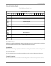
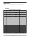
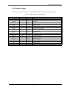
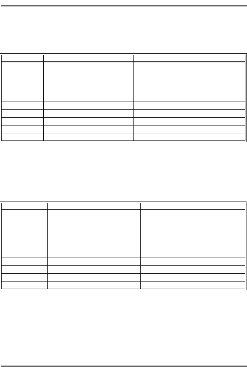
Table C-43. Serial Connector Pinouts (SPA and SPB)
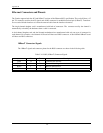
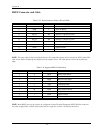
NOTE: The same cable for the second Serial Port for PC compatible systems can be used for the 4221 Condor. This
cable can be built or bought off-the-shelf from many computer stores. The cable pinout is shown in the following
table:
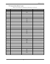
Table C-44. Suggested RS232 Cable Pinout
NOTE: Both RS232 ports on the Condor are configured as Data Terminal Equipment (DTE). With this connector
and cable configuration, a NULL modem cable may be required to connect a terminal to the board.
PIN
MNEMONIC TYPE DESCRIPTION
1 - - Unconnected (DCD)
2 DSR I Data Set Ready
3 RXD I Receiver Data Input
4 RCTS I/O RTS/CTS, (shorted to pin 6)
5 TXD O Transmitter Data Output
6 RCTS I/O RTS/CTS, (shorted to pin 4)
7 DTR O Data Terminal Ready
8 - - Unconnected (RI)
9 GND - Signal Ground
10 - - Unconnected
10-PIN
DB-25 PIN MNEMONIC DESCRIPTION
1 8 DCD Data Carrier Detect
2 6 DSR Data Set Ready
3 3 RXD Receiver Data Input
4 4 RTS Request to Send
5 2 TXD Transmitter Data
6 5 CTS Clear To Send
7 20 DTR Data Terminal Ready
8 22 RI Ring Indicator
9 7 GND Signal Ground
10 - - Unconnected