


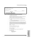

12-17
Configuring for Network Management Applications
CDP
Monitoring and Managing
the Switch
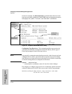
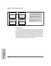
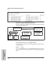
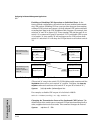
Using the example in figure 12-7:
The CDP Neighbor table for switches "A" and "B" would appear similar to
these:
Switch A:
Switch B:
Figure 12-8. Example of Viewable CDP Neighbor Table for Switches "A" and "B in
Figure 12-7
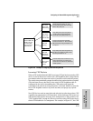
Thus, based on the CDP packets it receives, each CDP device maintains a per-
port data entry for each of its neighbors that are running CDP, but not for other
CDP devices that are accessible only through a CDP neighbor. (See the
relationship between switches A, B, and C in figure 12-7.) In other words, a
CDP device will have data on its immediate CDP neighbors (including those
reached through a device that is transparent to CDP), but not to other CDP
devices in the network.
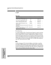
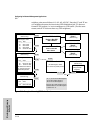
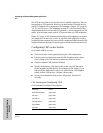
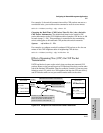
Table 12-1. How Devices Handle Incoming CDP Packets
(Note that no CDP devices appear on port B5, which is connected to a device on which CDP is present, but disabled.)
Status of Device Receiving
a CDP Packet
Action of Receiving Device
Running CDP Stores neighbor data in CDP Neighbor table. Does not forward CDP packet.
CDP Disabled Drops CDP packet. There is no CDP Neighbor table and no CDP neighbor data is stored.
No CDP Capability Forwards CDP packet out all ports except the port on which the packet was received.
Router Running CDP Stores neighbor data in CDP Neighbor table. Does not forward CDP packet.
Router with CDP (1) Disabled
or (2) Not CDP-Capable
Drops CDP packet.