


14-8
Port-Based Virtual LANs (VLANs) and GVRP
Port-Based Virtual LANs (Static VLANs)
Port-Based Virtual LANs
(VLANs) and GVRP
to ensure that multiple instances of DHCP or Bootp on different VLANs do not
result in conflicting configuration values for the switch. The primary VLAN
is the VLAN the switch uses to run and manage these features and data. In the
factory-default configuration, the switch designates the default VLAN
(DEFAULT_VLAN) as the primary VLAN. However, to provide more control
in your network, you can designate another VLAN as primary. To summarize,
designating a non-default VLAN as primary means that:
■ The stacking feature runs on the switch’s designated primary VLAN
instead of the default VLAN
■ The switch reads DHCP responses on the primary VLAN instead of on the
default VLAN. (This includes such DHCP-resolved parameters as the
TimeP server address, Default TTL, and IP addressing—including the
Gateway IP address—when the switch configuration specifies DHCP as
the source for these values.)
■ The default VLAN continues to operate as a standard VLAN (except, as
noted above, you cannot delete it or change its VID).
■ Any ports not specifically assigned to another VLAN will remain assigned
to the Default VLAN, regardless of whether it is the primary VLAN.
Candidates for primary VLAN include any static VLAN currently configured
on the switch. (A dynamic—GVRP-learned—VLAN that has not been con-
verted to a static VLAN cannot be the primary VLAN.) To display the current
primary VLAN, use the CLI show vlan command.
Note If you configure a non-default VLAN as the primiary VLAN, you cannot delete
that VLAN unless you first select a different VLAN to act as primary.
If you manually configure a gateway on the switch, it will ignore any gateway
address received via DHCP or Bootp.
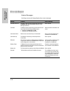
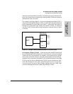
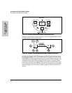
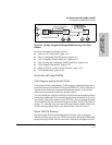
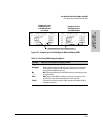
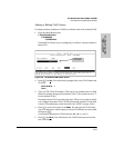
Per-Port Static VLAN Configuration Options
The following figure and table show the options you have for assigning
individual ports to a static VLAN. Note that GVRP, if configured, affects these
options and VLAN behaviour on the switch. The display below shows the per-
port VLAN configuration options. Table 14-1 briefly describes these options.