


KS152JB Universal Communications Controller
Technical Specifications
Kawasaki LSI USA, Inc. Page 18 of 120 Ver. 0.9 KS152JB2
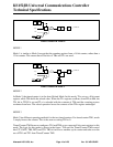
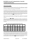
The interrupt flags are sampled in S5P2 of every machine cycle. In the next machine cycle, the
sampled interrupts are polled and their priority is resolved. If certain conditions are met then the
hardware will execute an internally generated LCALL instruction which will vector the process to
the appropriate interrupt vector address. The conditions for generating the LCALL are
1. An interrupt of equal or higher priority is not currently being serviced.
2. The current polling cycle is the last machine cycle of the instruction currently being executed.
3. The current instruction does not involve a write to IP or IE registers and is not a RETI.
If any of these conditions are not met, then the LCALL will not be generated. The polling cycle is
repeated every machine cycle, with the interrupts sampled at S5P2 in the previous machine cycle.
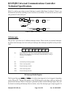
If an interrupt flag is active in one cycle but not responded to, and is not active when the above
conditions are met, the denied interrupt will not be serviced. This means that active interrupts are
not remembered, every polling cycle is new.
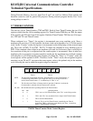
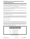
The processor responds to a valid interrupts by executing an LCALL instruction to the appropriate
service routine. This may or may not clear the flag which caused the interrupt. In case of Timer
interrupts, the TF0 or TF1 flags, are cleared by hardware whenever the processor vectors to the
appropriate timer service routine. In case of External interrupt, I
NT0 and INT1, the flags are
cleared only if they are edge triggered. In case of Local Serial interrupts, the flags are not cleared
by hardware. The hardware LCALL behaves exactly like the software LCALL instruction. This
instruction saves the Program Counter contents onto the Stack, but does not save the Program Sta-
tus Word PSW. The PC is reloaded with the vector address of that interrupt which caused the
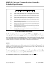
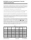
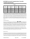
LCALL. These vector address for the different sources are as follows
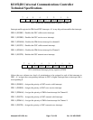
Table 5:
Priority
sequence
Priority
address
Priority
name
Interrupt
Symbolic
name
Interrupt
Symbolic
Name
Vector
Address
1 IP.0 PX0 IE.0 EX0 03H
2 IPN1.0 PGSRV IEN1.0 EGSRV 2BH
3 IP.1 PT0 IE.1 ET0 0BH
4 IPN1.1 PGSRE IEN1.1 EGSRE 33H
5 IPN1.2 PDMA0 IEN1.2 EDMA0 3BH
6 IP.2 PX1 IE.2 EX1 13H
7 IPN1.3 PGSTV IEN1.3 EGSTV 43H