


KS152JB Universal Communications Controller
Technical Specifications
Kawasaki LSI USA, Inc. Page 69 of 120 Ver. 0.9 KS152JB2
bits. Writing a one to a bit in AMSK0,1 masks out that corresponding bit in ADDR0,1.
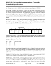
BAUD (94H) -GSC Baud Rate Generator - Contains the value of the programmable baud rate.
The data rate will equal (frequency of the oscillator)/((BAUD +1) x (8)). Writing to BAUD actu-
ally stores the value in a reload register. The reload register contents are copied into the BAUD
register when the Baud register decrements to 00H. Reading BAUD yields the current timer value.
A read during GSC operation will give a value that may not be current because the timer could
decrement between the time it is read by the CPU and by the time the value is loaded into its des-
tination.
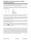
BKOFF(OC4H) - Backoff Timer -The backoff timer is an eight bit count-down timer with a clock
period equal to one slot time. The backoff time is used in the CSMA/CD collision resolution algo-
rithm. The user software may read the timer but the value may be invalid as the timer is clocked
asynchronously to the CPU. Writing to 0C4H will have no effect.
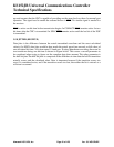
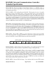
GMOD.0 (PR) - Protocol - If set, SDLC protocols with NRZI encoding and SDLC flags are used.
If cleared, CSMA/CD link access with Manchester encoding is used. The user software is respon-
sible for setting or clearing this flag.
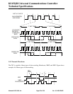
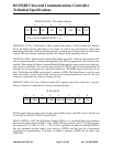
GMOD.1,2 (PL0,1) - Preamble length
PL1 PL0 LENGTH (BITS)
00 0
01 8
10 32
11 64
The length includes the two bit Begin Of Frame (BOF) flag in CSMA/CD but does not include the
SDLC flag. In SDLC mode, the BOF is an SDLC flag, otherwise it is two consecutive ones. Zero
length is not compatible in CSMA/CD mode. The user software is responsible for setting or clear-
ing these bits.
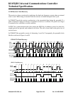
GMOD.3 (CT)-CRC Type - If set, 32 bit AUTODINII -32 is used. If cleared, 16 bit CRC-CCITT
is used. The user software is responsible for setting or clearing this flag.
GMOD.4 (AL) - Address Length - If set, 16 bit addressing is used. In 8 bit mode a match with any
of the 4 address registers will be accepted (ADR0, ADR1, ADR2, ADR3). “Don’t Care” bits may
be masked in ADR0 and ADR1 with AMSK0 and AMSK1. In 16 bit mode, addresses are
matched against “ADR1:ADR0” or “ADR3: ADR2”. Again, “Don’t Care” bits in ADR1:ADR0
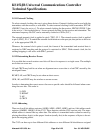
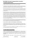
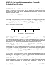
XTCLK
M1
M0 AL
CT
PL1
PL0
PR
7
65 4
3
21
0
GMOD(84H)