


KS152JB Universal Communications Controller
Technical Specifications
Kawasaki LSI USA, Inc. Page 25 of 120 Ver. 0.9 KS152JB2
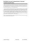
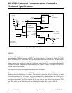
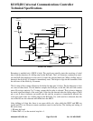
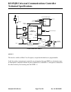
Reception is enabled only if REN is high. The serial port actually starts the receiving of serial
data, with the detection of a falling edge on the RxD pin. The 1-to-0 detector continuously moni-
tors the RxD line sampling it at the rate of 16 times the selected baud rate. When a falling edge is
detected, the divide by 16 counter is immediately reset. This helps to align the bit boundaries with
the rollovers of the divide by 16 counter.
The 16 states of the counter effectively divide the bit time into 16 slices. The bit detection is done
on a best of three basis. The bit detector samples the RxD pin, at the 8th, 9th and 10th counter
states. By using a majority 2 of 3 voting system, the bit value is selected. This is done to improve
the noise rejection feature of the serial port. If the first bit detected after the falling edge of RxD
pin, is not 0, then it indicates an invalid start bit, and the reception is immediately aborted. the
serial port again looks for a falling edge in the RxD line. If a valid start bit is detected, then the
rest of the bits are also detected and shifted into the SBUF.
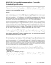
After shifting in 8 data bits, there is one more shift to do, after which the SBUF and RB8 are
loaded and RI is set. However certain conditions must be met before, The loading and setting of
RI can be done.
1. RI must be 0 and
2. Either SM2 = 0, or the received stop bit = 1.
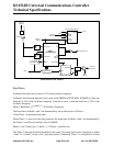
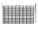
SOUT
STOP
PARIN
START
LOAD
CLOCK
TX START
TX CLOCK
Transmit Shift Register
16
SIN
D8
PAROUT
CLOCK
BIT
DETECTOR
RX CLOCK
RX SHIFT
1-TO-0
DETECTOR
16
RX
SBUF
RB8
LOAD
SBUF
START
Read
SBUF
TX SHIFT
TI
RI
SERIAL
CONTROLLER
2
SMOD
01
Write to
SBUF
Internal
Data Bus
0
1
Internal
Data Bus
RxD
TxD
Serial Interrupt
Timer 1
Overflow
Receive Shift Register
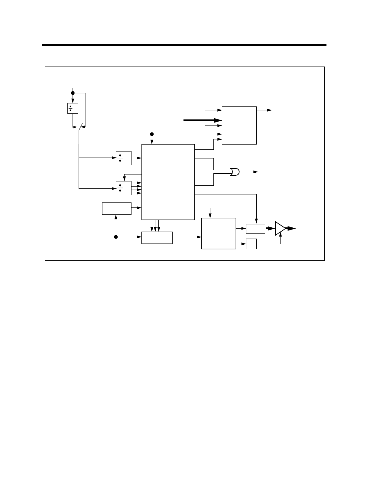
Serial Port Mode 1