


LaserSpeed 8000-3 Instruction Handbook
Installing the System
Part No. 93463 / Drawing No. 0921-01561 Page 16 of 221 Revision A (Sep 2007)
Installing the System
This section describes mounting, alignment and other installation concerns for
the LS8000-3.
The installation can be broken down into five steps:
Mounting the gauge
Aligning the gauge
Connecting power to the gauge
Connecting to the outputs
Maximizing gauge performance
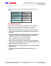
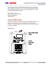
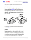
Mounting the Gauge
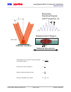
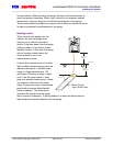
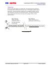
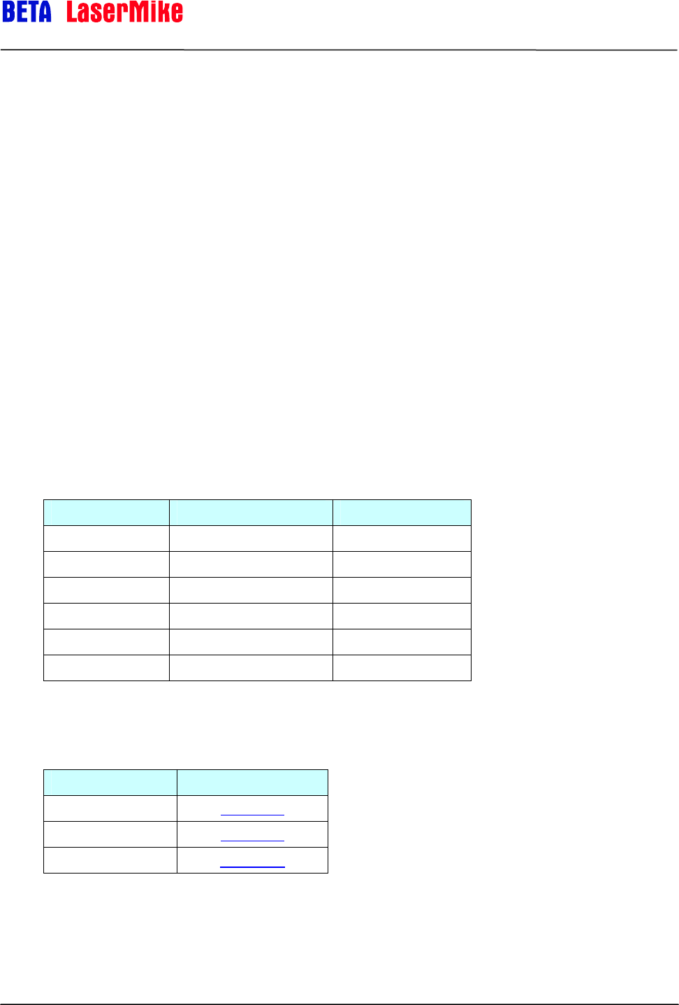
The LS8000-3 must be placed at the correct standoff distance from the moving
material. A series of LaserSpeed gauges provide a variety of standoff
distances and depths of field.
Model Standoff Distance Depth of Field
LS8000-303 300mm (11.8 in) 35mm (1.4 in)
LS8000-306 600mm (23.6 in) 50mm (2.0 in)
LS8000-310 1000mm (39.4 in) 100mm (3.9 in)
LS8000-315 1500mm (59.0 in) 200mm (7.9 in)
LS8000-320 2000mm (78.7 in) 200mm (7.9 in)
LS8000-325 2500mm (98.4 in) 200mm (7.9 in)
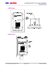
Please refer to the following Appendices for mounting dimensions and
installation drawings:
Model Section
LS8000 Appendix A
LS8000E Appendix B
LS8000X Appendix C