


LaserSpeed 8000-3 Instruction Handbook
Interfacing with the LS8000-3
Part No. 93463 / Drawing No. 0921-01561 Page 59 of 221 Revision A (Sep 2007)
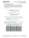
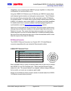
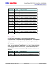
0 2 4 6 8 10 12 14 16
0
0.1
0.2
0.3
0.4
0.5
0.6
0.7
0.8
0.9
1
Quality Factor
Analog Output / Volts
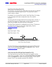
Analog Output vs Quality Factor
Voltage = Measured Analog Output Voltage
Note that when the output voltage is at either limit, the exact speed cannot be
determined. If the exact speed is always required, be sure to set the Full
Scale Velocity setting to a value higher than what can normally be
encountered.
The analog port can also be configured to
output the QF on a 0–1 V scale by setting
the Full Scale Velocity to zero using a serial
command or LaserTrak software. In this
case, the analog output reads 0V when
the QF is 0 and 1V when the QF is 15.
When the Analog Output is configured to
output Quality Factor, the Quality Factor
can be calculated with the following
equation:
15×= VoltagetorQualityFac
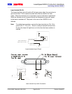
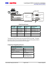
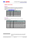
When connecting to the Analog Output Voltage, the Analog Output Voltage
and Analog Output Ground should be on a separate twisted pair inside of a
shielded cable. Connect a 0.1µF capacitor across the load end of the cable
(the end opposite the gauge) to reduce noise caused by other signals in the
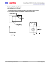
cable. See the following wiring example:
Gauge DB9
0.1 Fµ
1000
minimum
Ω
Analog Output Ground (Pin 7)
Analog Output+ (Pin 6)
Analog Output Cable
Shielded, Twisted Pair
Cable Jacket
Cable Shield
Terminate Shield/Drain Wire to backshell of DB9 connector
Terminate Shield/Drain Wire to
Chassis Ground
Analog Output Wiring Example
Measurement Synchronization Input (Pins 8-9)
In many AGC applications, particularly mass flow control, it is desirable to
synchronize the sampling periods of all gauges in the system. This is done by
connecting an LS8000-3 I/O Module to each LS8000-3 in the system (for