


LaserSpeed 8000-3 Instruction Handbook
Installing the System
Part No. 93463 / Drawing No. 0921-01561 Page 26 of 221 Revision A (Sep 2007)
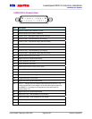
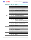
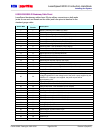
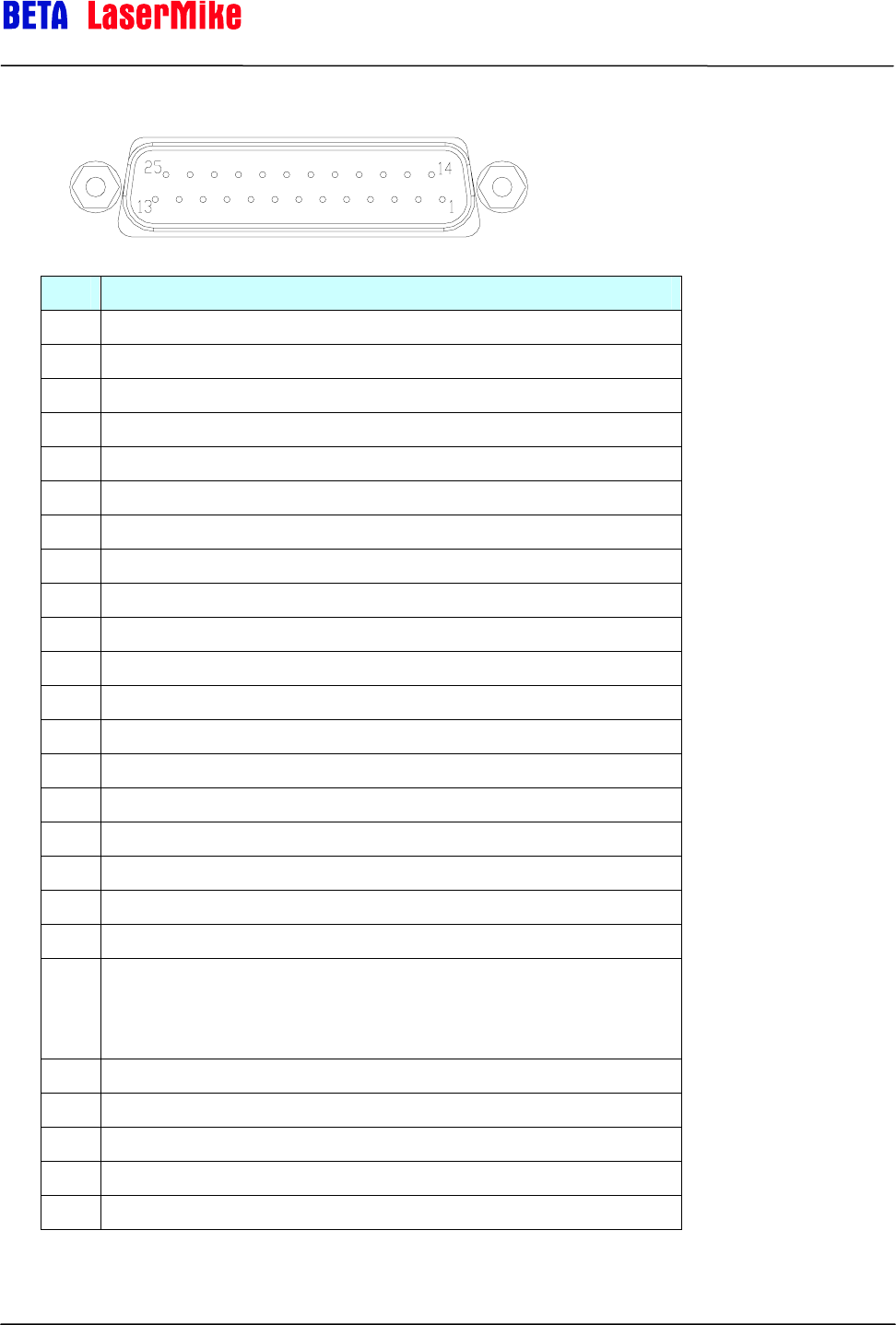
LS8000-3 25-Pin Connector Pinout
Pin Description
1 RS-232 Transmit (from LS8000-3 to host)
2 RS-232 Receive (from host to LS8000-3)
3 Phase A True – High Speed Output (RS-422 Drivers)
4 Phase A False – User Scaleable (5-24V Output)
5 Phase A False – High Speed Output (RS-422 Drivers)
6 Phase B True – User Scaleable (5-24V Output)
7 Phase B True – High Speed Output (RS-422 Drivers)
8 Phase B False – User Scaleable (5-24V Output)
9 Phase B False – High Speed Output (RS-422 Drivers)
10 Material Present Input (5-24V Input)
11 Signal Ground for Inputs/Outputs/Serial
12 Power Ground for 24V Input
13 Power Ground for 24V Input
14 Measurement Direction Input (5-24V Input)
15 Phase A True – User Scaleable (5-24V Output)
16 Laser Interlock (Connect to Signal Ground to Turn On Laser)
17 Shutter Control (Connect to Signal Ground to Open Shutter)
18 Length Reset Input (5-24V Input)
19 Signal Ground for Inputs/Outputs/Serial
20 User V
IN
– Voltage input for Isolated Pulse Outputs (5 to 28V DC). The
voltage supplied will be the voltage level of the pulse outputs supplied by
the LS8000-3. If a Voltage is not supplied, the pulse outputs will be
approximately 4.5V.
21 Signal Ground for Inputs/Outputs/Serial
22 Index Pulse True - User Scaleable (5-24V Output)
23 Index Pulse False - User Scaleable (5-24V Output)
24 24V Fused Input
25 24V Fused Input