


LaserSpeed 8000-3 Instruction Handbook
Installing the System
Part No. 93463 / Drawing No. 0921-01561 Page 31 of 221 Revision A (Sep 2007)
Maximizing Performance
The system is now at the point where it can be powered on and the laser
activated so beams are emitted from the front of the gauge. Be sure that the
laser interlock and shutter control circuits are functioning properly.
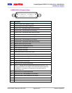
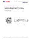
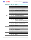
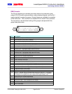
When Pin 16 is connected to GND (Pin 11, 19, or 21), the laser
becomes operational.
When Pin 17 is connected to GND (Pin 11, 19, or 21), the shutter will
open.
Check the key switch to verify the laser power can be controlled.
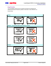
Warning: Avoid exposure to the beam. Never look directly into the laser
beams, even when wearing protective eyewear. Eye damage
could result.
Note: There may be some delay time between when the system is powered
on, and when the laser comes on. There is a 7 second delay after
power is applied to the laser (key switch on, laser interlock closed)
before the laser turns on. The laser will also not turn on until the
laser temperature controller stabilizes. This may take a few minutes
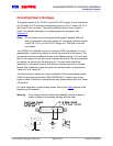
after power is initially applied. The standoff distance can be verified
by using a business card or sheet of white paper. Both beams can
be viewed and the area where the beams overlap is the active
measurement region. The location where the overlap of the beams is
smallest is the center of the measurement region. This location
corresponds to the standoff distance and is where the beams should
intersect the product.
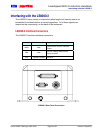
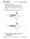
The configuration and setup of the gauge can be verified and/or changed
using the supplied LaserTrak Software or directly using the serial commands
listed in the Communication Protocol
section. Utilizing either one of these
approaches requires a computer with an RS-232 serial port connected to pins
1 and 2 of the 25-pin D-sub connector, or an RS-422 serial port connected to
pins 1-4 of the 9-pin D-sub connector.
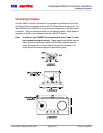
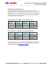
Once proper communication is established (see the See the LaserTrak
Software section for help), it is recommended to check the Quality Factor (QF).
QF can be checked using LaserTrak, and viewing the chart recorder screen. If
it is below 15, try to move the product or the gauge slightly (adjust the
standoff) and look for improvements in QF. Once QF is maximized, change
the line speed and look for a corresponding velocity change on the chart
recorder.