


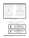

2. Wire the secondary clocks to P1 and/or to P2. See Wiring Secondary Clocks on
page B-2 for complete instructions.
Note:
You may need to add external metal-oxide varistors (MOVs) or diodes to synchronize
a specific clock type. See the clock wiring diagrams in Appendix B.
3. Wire the signaling devices to P3. See Typical Signal Device Wiring on page C-3.
Note:
If the master clock is not connected to any secondary clocks, signaling devices can be
wired to P1 and P2.
4. Although the master clock is fused internally to protect its electronics, the incoming
AC line must also be fused as required by your local electrical code. Dukane recom
-
mends connecting the unit to a dedicated 10-amp circuit.
5. Turn the toggle switch in the power supply to the ON position.
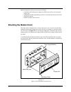
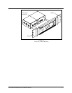
6. Complete any mounting steps in the previous section, Mounting the Master Clock
on page 1-2.
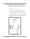
Synchronizing Non-Compatible Clocks by External Pulse
The master clock can synchronize to other systems if necessary. For example, you have a
non-compatible time clock that cannot be synchronized by the master clock, but it has a
built-in bell ringer. By shorting terminals 7 and 8 on terminal block P4, or terminals 6
and 7 of the communications terminal on the back of the display unit, the master clock
will immediately reset to 00:00 (midnight). If you can program the other device to close
its circuit at 00:00 (midnight) then the two systems will remain reasonably in sync.
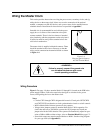
—WARNING—
DO NOT apply power to the external
pulse-sync terminals. Simply close
the circuit for 1–5 seconds.
1-10
24A715/24A715M Master Clock Installation Manual