


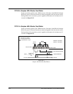
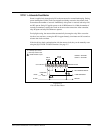
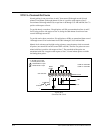
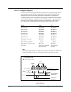
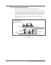

TYPE 15—Straight Frequency
Clock correction and bell circuit operations are generated by sequentially applying vari
-
ous frequencies onto the 120Vac. Each bell and clock correction circuit has its own
frequency and a receiver circuit that applies the associated bell or clock frequency
(3,510Hz normally used for clock signals). The daylight saving feature advances clocks
correctly but has no means, other than normal 12-hour correction, to correct secondary
clocks at 2:00 AM. The time sequence of applying the frequencies to the 120Vac is
shown below and is controlled by the bell and system relays in the master clock.
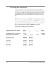
Relay From To
Bell Circuit 1 HH:MM:00 HH:MM:05
Bell Circuit 2 HH:MM:05 HH:MM:10
Bell Circuit 3 HH:MM:10 HH:MM:15
Bell Circuit 4 HH:MM:15 HH:MM:20
Bell Circuit 5 HH:MM:20 HH:MM:25
Bell Circuit 6 HH:MM:25 HH:MM:30
K5 (hourly correction HH:57:54 HH:58:02
K5 (12-hour correction) 5:57:54 5:58:08
K6 (hourly and 12-hour corr.) HH:57:00 HH:59:00
K6 (bells) 35th second of minute
previous to bell
30th second of
bell time
Note:
Bells must be programmed one minute ahead of desired time. Bells are inhibited dur-
ing the 58th minute and will not work during manual clock corrections either.
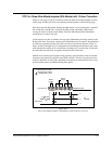
B-20
24A715/24A715M Master Clock Installation Manual
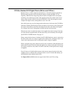
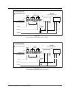
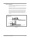
12345678
CLK 1 OR CLK2
x
x
x
x
RELAY
K6 (K8)
RELAY
K5 (K7)
II
MASTER CLOCK
FIELD CONNECTIONS
X = Normally open contact
I = Normally closed contact
AC RTN
10 ASB MAX.
120Vac
3,510 HZ SIGNAL
GENERATOR
1
= V250LA4 MOV or equal
1
1
GENERATOR
PRESTART
Figure B-17
Straight Frequency