


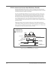

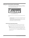
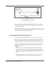
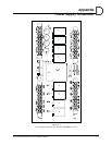


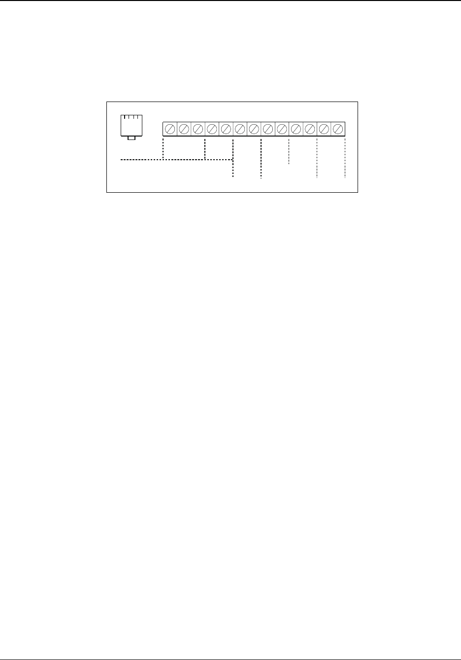
Wiring the Communications Terminal Block
The communications terminal block is on the back of the display unit. See Figure C-6.
It is used to connect the optional modem, a computer, any RS-485 devices, and a power
source for the optional remove schedule selector.
When making connections to the communications terminal block, keep the following in
mind:
•
Twisted-pair (Cat-3/Cat-5) wire connects directly to the terminal block, with up to
two wires per position.
•
The pulse-sync input is the same as provided in the power supply. A one-second
(minimum) dry-contact switch closure across the terminals will cause the master
clock to reset the time to 12:00 AM of the nearest date.
•
Grounds (GND) are signal grounds, not chassis grounds.
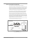
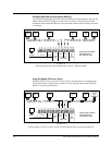
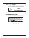
Wiring the Host Communications Terminals
The host communications terminals on the communications terminal block include:
RS-232—Three terminal block contacts for RS-232 communications with an IBM-
compatible computer running the optional Lathem MasterLink programming software.
Notes:
This terminal is typically used for a permanent connection to a computer. To make a
cable to connect the computer to the RS-232 terminals, see Figure C-7 on page C-5.
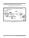
For a temporary computer connection, see Connecting a Computer to the Front Ac
-
cess Port on page C-8.
C-4
24A715/24A715M Master Clock Installation Manual
12345 101112136789
TxD RxD
D
+
D
-
G
N
D
G
N
D
S
Y
N
C
D
+
D
-
D
+
D
-
~
~
~
RS-232
RS-485
SYNC
OUT
SYNC
IN
12V~
AC
OUT
250ma
MODEM
HOST COMMUNICATIONS
PULSE
SYNC
RS-485
DATA SYNC
Figure C-6
The Communications Terminal Block