


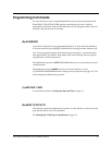
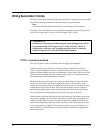
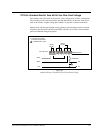
Please note that the relay contacts used in the CLK2 circuit are rated at 10 amps. The
combined load of the correction circuit and the run circuit should not exceed 8 amps. In
general, 20–35 analog clocks can be operated on a single string. This number depends on
the clock style and the distances involved. To estimate clock loads for Dukane 24SS se
-
ries clocks, see the Dukane Analog Clock Installation Guide (document number
402-455).
24A715/24A715M Master Clock Installation Manual
B-3
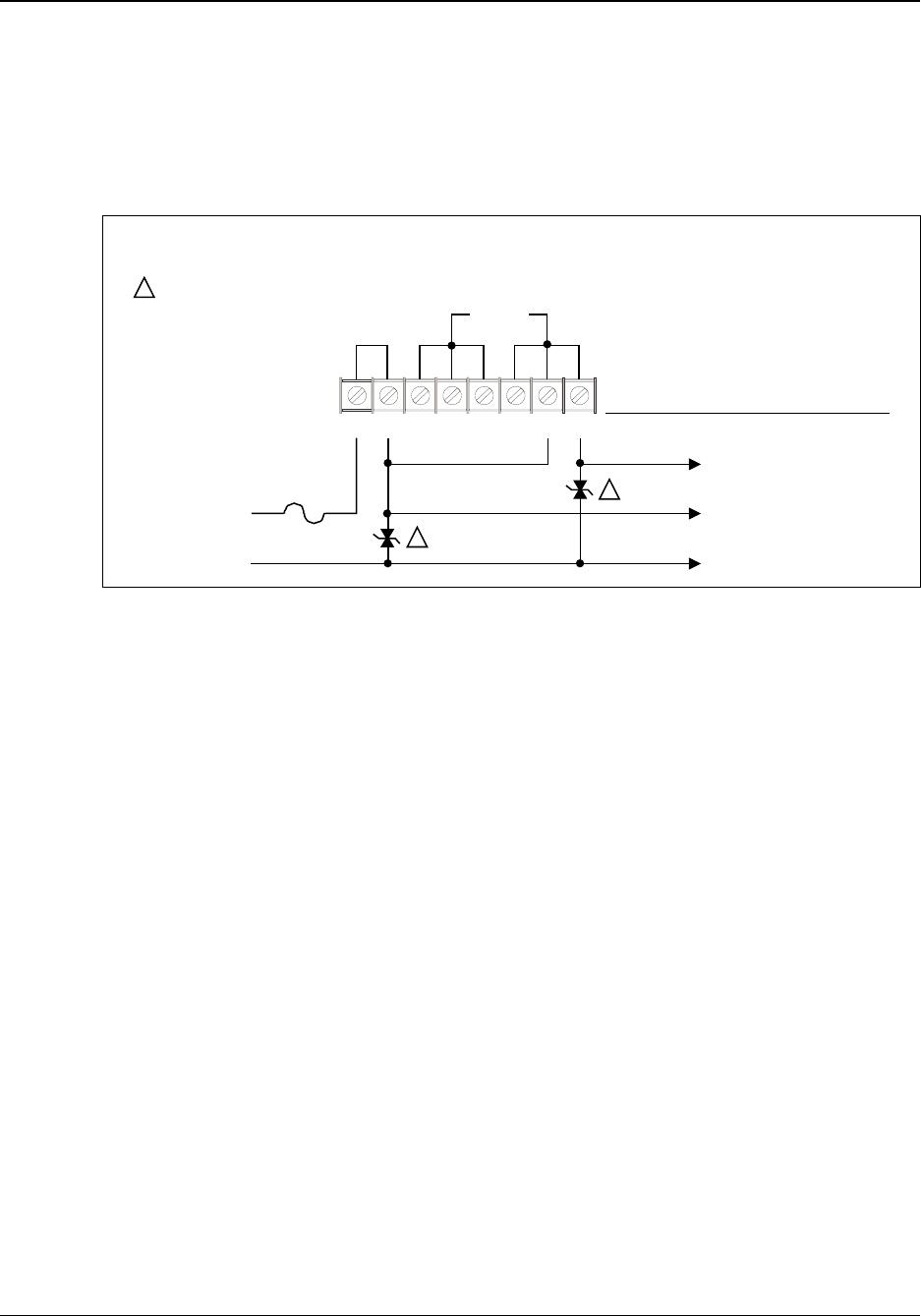
12345678
CLK1 OR CLK2
x
x
x
x
RELAY
K6 (K8)
RELAY
K5 (K7)
II
MASTER CLOCK
FIELD CONNECTIONS
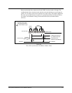
X = Normally open contact
I = Normally closed contact
24 OR 120 VAC
10 ASB MAX.
NEUTRAL
CORRECTION CIRCUIT
TO CORRECTION COIL
RUN CIRCUITTO
ANALOG CLOCK MOTOR
1
1
1
= V250LA4 MOV or equal
NEUTRAL
Figure B-1
Three-Wire Synchronous (59th Minute, Dukane 24SS)