


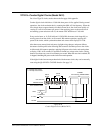

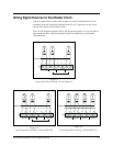
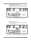


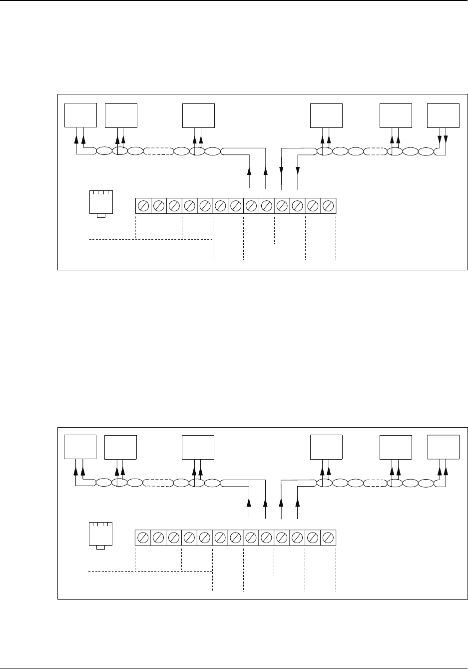
Wiring RS-485 Time Synchronization Devices
Up to 30 RS-485 Data Synchronization Devices (DSDs) can be connected to the sync ter
-
minals. Since the SYNC IN port can send as well as receive, 30 extra devices can be
connected. If more than 60 DSDs are to be connected, another master clock must be used
as a booster.
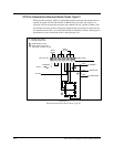
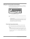
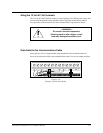
Using the Master Clock as a Slave
Since the SYNC IN port can send as well as receive, 30 extra devices can connect here.
If you already have a master source, connect it and its string of clocks to the SYNC IN
port for a total of up to 60 devices.
C-6
24A715/24A715M Master Clock Installation Manual
MASTER
CLOCK
-
12345 101112136789
TxD RxD
D
+
D
G
N
D
G
N
D
S
Y
N
C
D
+
D
-
D
+
D
-
~
~
RS-232
RS-485
SYNC
OUT
SYNC
IN
12V~
AC
OUT
250ma
MODEM
HOST COMMUNICATIONS
PULSE
SYNC
RS-485
DATA SYNC
+-
RS-485
DSD
RS-485
DSD
+-
RS-485
DSD
+-
RS-485
DSD
+-
RS-485
DSD
+-
+-
PORTS ARE LOCATED
ONTHEBACKOF
THE DISPLAY UNIT
Figure C-8
Synchronizing RS-485 Time Synchronization Devices Without a Buffer
-
12345 101112136789
TxD RxD D
+
D
G
N
D
G
N
D
S
Y
N
C
D
+
D
-
D
+
D
-
~
~
~
RS-232
RS-485
SYNC
OUT
SYNC
IN
12V~
AC
OUT
250ma
MODEM
HOST COMMUNICATIONS
PULSE
SYNC
RS-485
DATA SYNC
RS-485
DSD
RS-485
DSD
RS-485
DSD
RS-485
DSD
RS-485
DSD
RS-485
DSD
+-
+-
+-
+-
+-
+-
PORTS ARE LOCATED
ONTHEBACKOF
THE DISPLAY UNIT
Figure C-9
Using the Master Clock as a Slave to Allow 30 Extra RS-485 Time Synchronizing Devices