


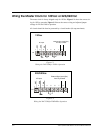

Wiring Signal Devices to the Master Clock
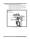
Typically, signal devices (such as bells or lights) are wired to terminal block P3. If no
secondary clocks are connected to terminal blocks P1 or P2, signal devices can also be
wired to those blocks. See the figures below.
Zone 7A and 7B operate together, and 5A and 5B operate together. You can use either of
these circuits for bells. All circuits should be fused or protected by a circuit breaker
(10A maximum).
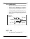
24A715/24A715M Master Clock Installation Manual
C-3
12
3
4
5
6
7
8
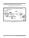
Zone 8 Zone 7A Zone 7B
P1
Voltage IN
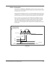
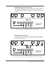
Zone 7A & 7B Operate Together
Figure C-3
Typical Signal Device Wiring—Terminal Block P1
12
3
4
5
6
7
8
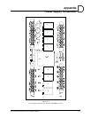
Zone 6 Zone 5A Zone 5B
P2
Voltage IN
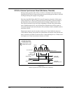
Zone 5A & 5B Operate Together
Figure C-4
Typical Signal Device Wiring—Terminal Block P2
12
3
4
5
6
7
8
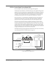
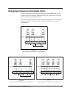
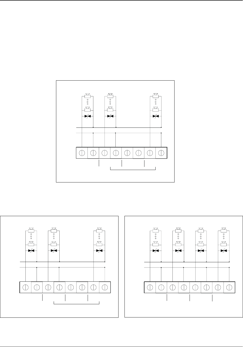
Zone 1 Zone 2 Zone 3 Zone 4
P3
Voltage IN
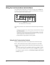
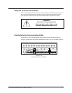
Figure C-5
Typical Signal Device Wiring—Terminal Block P3